
Technical data

infraSchwank D / calorSchwank D - shape U
5
Version 004 infra_calor D shape U Australia 43/13 Technical specification subject to change
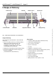
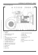
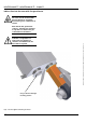
Structure of the burner unit
Fig. 2: Burner unit
1. Controller
2. Air differential pressure switch
3. Fan air restrictor plate
4. Fan
5. Air baffle plate (only 15 / 20 / 30 / 40U)
6. Gas combination valve
(single-, two-stage or modulating)
7. Test nipple connection pressure
8. Test nipple nozzle pressure
9. Adjustment screw nozzle pressure
10. Adjustment screw start step valve
11. Inspection glass
12. Burner cup
13. Burner nozzle
14. Ignition and ionisation electrode
15. Ignition cable
16. Ionisation cable
17. 3-pin power supply socket
18. Locking screw
19. Venturi
20. Burner baffle (only 15 / 20 / 30 / 40U)
21. Gasket