
Technical data

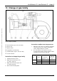

infraSchwank D / calorSchwank D - shape U
30
Version 004 infra_calor D shape U Australia 43/13 Technical specification subject to change
14 Accessories
Ball guards
Ball protection grids acc.18032-3 for using heaters in
sport halls (grid 40x40mm).
Delivery scope
Mounting set complete for each type of heater
existing of:
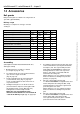
infra/calorSchwank D shape U 15U 20U 30U 40U
Ball protection grid L=1443mm
Ball protection grid L=1843mm 2x 2x 2x
Ball protection grid L=2203mm 1x
Ball protection grid L=2963mm 1x 1x 2x
Protection grid burner top 1x 1x 1x 1x
Front protection cover burner 1x 1x 1x 1x
Protection grid burner end side 1x 1x 1x 1x
End bracket with stud bolts M8 1x 1x 1x 1x
Holding bracket (1x infra D +1x calor D) 1x 1x 1x
Angled bracket with stud bolt M8 4x 4x 6x 8x
Clamp 6x 6x 8x 10x
Set fixing material 1x 1x 1x 1x
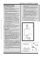
Assembling
(Description for heater infra/calorSchwank D 30 U,
other types similar)
1. Mounting heater as usually acc. manual
(see chapter 9, page 16 - 19).
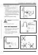
2. Fix end bracket at inner side of turnaround box,
open and close again 4 nuts M8
(Fig. 30, page 32)
3. Fix two angled brackets at each tube hanger
(screws M8 x 60, nuts) (Fig. 31, page 32)
Screw on angled brackets at the inner holes of
suspension bracket.
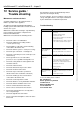
4. Holding bracket put loose on the first reflector
(view from burner unit) and screw together with
two angled brackets (screws M8 x 60, nuts),
holding bracket remain axially movable
NOTE: Use the right holding bracket –
difference infraSchwank D or calorSchwank D
– both in the delivery scope (Fig. 32, page 32)!
5. Assembling segments ball protection grids starts
on the turnaround box (last suspension bracket
for shape L). Put first segment ball protection
grid L=2963 mm from below on end bracket
and angled brackets of the next suspension
bracket – Put clamps on stud bolts M8 and
mount with self-locking nuts
Mount clamp loose on one stud bolt of angled
bracket for further assembling next protection
grid (Fig. 33, page 32).
6. Put next segment ball protection grid
L= 1843mm from below on angled brackets and
mount clamp with self-locking nuts M8, clamp
and angled bracket connect two segments ball
protection grid to each other.
Mount clamp loose on one stud bolt of angled
bracket for further assembling next protection
grid.
7. Put next segment ball protection grid
L= 1843mm from below on angled brackets and
mount clamps with self-locking nuts M8
Last segment ball protection grid L= 1843mm
protects the burner unit at the bottom.