BROCSCH115.
Contents 1 2 Introduction ................................................................................................................ 3 Your Safety ................................................................................................................ 3 Notes for your safety .................................................................................................................... 3 3 4 Scope of Delivery ..............................................................................
infraSchwank D / calorSchwank D - shape U 1 Introduction Thank you for choosing a high efficiency SCHWANK radiant tube. Your infraSchwank D / calorSchwank D is a modern and low-pollution tube heater for economic and comfortable heating of industrial and commercial buildings. The design and operation of the heater are according to the requirements of the existing standards.
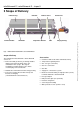
infraSchwank D / calorSchwank D - shape U 3 Scope of Delivery reflector long turnaround box turbulator reflector short suspension bracket burner unit tube flange packing Radiant tube infraSchwank D / calorSchwank D 20U Scope of Delivery The radiant tube infraSchwank D / calorSchwank D consists of: Accessories Control box with on/off switch and indicator lamp Burner-unit with gas-burner, pre-mixing chamber, ignition and control unit, firing device, gas combination valve (single-, two-stage or
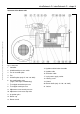
infraSchwank D / calorSchwank D - shape U Version 004 infra_calor D shape U Australia 43/13 Technical specification subject to change Structure of the burner unit Fig. 2: Burner unit 1. Controller 2. Air differential pressure switch 3. Fan air restrictor plate 4. Fan 5. Air baffle plate (only 15 / 20 / 30 / 40U) 6. Gas combination valve (single-, two-stage or modulating) 14. Ignition and ionisation electrode 15. Ignition cable 16. Ionisation cable 17. 3-pin power supply socket 18. Locking screw 19.
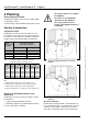
infraSchwank D / calorSchwank D - shape U 4 Planning Do not place articles on or against this appliance. Room temperature control Do not use or store flammable materials near this appliance. Radiant tube heating-systems must be equipped with a temperature control. Do not spray aerosols in the vicinity of this appliance while it is in operation. Section heating is allowed without temperature control.
infraSchwank D / calorSchwank D - shape U Positioning The radiant tube can be mounted with chains (links min. 4 mm) adjustable steel cable (Schwank accessories) If you chose chains please use bolts with lock nuts for fixing the chain to the suspension bracket. wrong Version 004 infra_calor D shape U Australia 43/13 Technical specification subject to change The radiant tube has to be fixed by vertical chains etc. to the roof or to supporting devices.
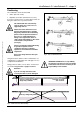
infraSchwank D / calorSchwank D - shape U Air supply / Exhaust Requirements Air supply / exhaust systems The calculation of air supply / exhaust requirements of a building heated by radiant tube heaters is subject of Australia Standard AS 5601. Please follow local bylaws as well. For the radiant tube infraSchwank D / calor SchwankD the following air supply / exhaust systems are possible: Please see the max. lengths of combustion air supplyand exhaust flue pipe on page 9 (Tab 3, point 3). 1.
infraSchwank D / calorSchwank D - shape U 2. Exhaust flue with individual exhaust system combustion air from inside the room (Type B23) 4. Exhaust flue with flue collecting system and central flue fan (according to EN 777, Type D) Only use this system in rooms with no air pollution and without relevant pressure differences to outside. Otherwise use type C. The heating installation must not exceed 10 radiant tubes.
infraSchwank D / calorSchwank D - shape U Indirect flue into the room with flue gas diverter Installation with indirect flue into the room must be mounted with flue gas diverter to avoid flow back of flue gas in combustion air stream. Note that the flue gas diverter (code no. 126 7018 0) is mounted in a position so that the flue gas is diverted from the burner.
infraSchwank D / calorSchwank D - shape U 5 Legal Requirements 6 Operating We recommend that these installation guidelines should be observed with the relevant Building Standards Regulations of your country. Comply with any local by-laws and the current IEE Wiring Regulations.
infraSchwank D / calorSchwank D - shape U 7 Technical specification Appliance Automatic heating device, heat transfer by mean of infrared dark radiation. Fuel Types Natural gas Propane Electrical connection Single phase A.C. 230 V, N, PE - 50Hz (cycles) (approx. 80 VA) Power supply for the heater and fan are connected to the socket of the burner box. To set the burner box free of voltage, it is only necessary to remove the plug of the power supply. Max. connection pressure Natural Gas: 5.
infraSchwank D / calorSchwank D - shape U infraSchwank D / calorSchwank D 30U (all dimensions in mm) Version 004 infra_calor D shape U Australia 43/13 Technical specification subject to change infraSchwank D / calorSchwank D 40U (all dimensions in mm) Fig 9: Measurements infraSchwank D / calorSchwank D 30U and 40U (view from below) 13
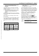
infraSchwank D / calorSchwank D - shape U Technical data for single and two-stage regulation Gas 15U Natural gas Gas consumption [MJ/h] 1) single state Propane 2) infraSchwank D / calorSchwank D 20U 30U 40U 59.9 75.9 115.9 155.8 Gas consumption [MJ/h] 2-stage/modulating max./min. 59.9 - 44.7 75.9 - 57.2 115.9 - 87.9 155.8 - 119.9 Gas consumption [MJ/h] 2-stage/modulating max./min. 58.7 74,4 113.5 152.6 Gas consumption [MJ/h] 2-stage/modulating max./min. 58.7 - 43.8 74.4 - 56.0 113.
infraSchwank D / calorSchwank D - shape U 8 Operating description Start-up If heat demand exists, the fan will start up automatically. A differential pressure arises in the burner box, which is reported to the ignition unit via the differential pressure switch. After a pre-purge period of about 25 seconds the automatic ignition starts (max. ignition time 5 sec.). The twin solenoid valve with pressure regulator opens the gas supply to the burner in 2 steps.
infraSchwank D / calorSchwank D - shape U 9 Assembly instructions infraSchwank D / calorSchwank D 15U Tools you need • hexagonal wrench or ratchet (width: 10, 13) • socket wrench (width: 7 and 8) Note before mounting Note the distance measure of suspension brackets. Flanges are mounted with flange packing (each 4 screws/washers/lock washers/nuts M8). Start mounting the heater at the turnaround box connection.
infraSchwank D / calorSchwank D - shape U Assembly infraSchwank D / calorSchwank D 20U Tools you need • hexagonal wrench or ratchet (width: 10, 13) • socket wrench (width: 7 and 8) Note before mounting Note the distance measures of suspension brackets. Flanges are mounted with flange packing (each 4 screws/washers/lock washers/nuts M8).
infraSchwank D / calorSchwank D - shape U Assembly infraSchwank D / calorSchwank D 30U Tools you need • hexagonal wrench or ratchet (width: 10, 13) • socket wrench (width: 7 and 8) hand rivet tool, drill machine, drill 4.9mm Note before mounting Fig. 12: Mounting of infraSchwank D / calorSchwank D 30U (all dimensions in mm) Flue gas diverter 18 Version 004 infra_calor D shape U Australia 43/13 Technical specification subject to change Note the distance measures of suspension brackets.
infraSchwank D / calorSchwank D - shape U Assembly infraSchwank D / calorSchwank D 40U Tools you need • hexagonal wrench or ratchet (width: 10, 13) • socket wrench (width: 7 and 8) Version Version004 004infra_calor infra_calorDDshape shapeUUAustralia Australia43/13 43/13Technical Technicalspecification specificationsubject subjecttotochange change Version 004 infra_calor D shape U Australia 43/13 Technical specification subject to change Note before mounting Note the distance measures of suspension
infraSchwank D / calorSchwank D - shape U 10 Installation instructions pressure drop value of the Schwank gas-pipe-systems see table 7. Minimum connection pressures in front of valve infraSchwank D / calorSchwank D shape U Danger of fire and explosion! Unprofessional handling of gas pipes, gas connections and the appliance can produce gas leaks. It is highly dangerous if gas is ignited! Working on gas pipes and the appliances is only allowed by approved installers.
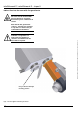
infraSchwank D / calorSchwank D - shape U Note the following points while installing the gas-pipe-system: Use only gas lines as per national standards. 430 mm (+/- 10%) Never hang heaters on the gas pipes. Mount a manual gas cock upstream of every radiant tube. Close all gas cocks before carrying out the leak test and disconnect the connection between the gas cock and the burner to avoid damages to the gas regulator and gas combination valve.
infraSchwank D / calorSchwank D - shape U Gas connection has to be positioned in the axle of the heater. Otherwise torsional forces will operate on the hose! Avoid twisting of the flexible hose! (When tightening the union, counter hold the nipple on the hose.) Pay attention that the flexible hose will not be mechanically damaged by tools etc. Do not buckle the hose. Do not mount damaged flexible hoses! Damaged hoses can break due to the movement of the heater.
infraSchwank D / calorSchwank D - shape U Gas valve VK 4105C 1 Burner unit PE 2 L PE N Control box Thermocontrol Plus M / unoSchwank L single-stage operation N PE Electrical supply 1~230Volt, 50Hz, N, PE Version Version004 004infra_calor infra_calorDDshape shapeUUAustralia Australia43/13 43/13Technical Technicalspecification specificationsubject subjecttotochange change Version 004 infra_calor D shape U Australia 43/13 Technical specification subject to change Fig.
infraSchwank D / calorSchwank D - shape U GVK VK 4105N with modulating lifting magnet Burner unit 1 PE 2 o Modulation Box (distance to burner unit < 1,5m) Time delay 1minute ignition for max.
infraSchwank D / calorSchwank D - shape U 11 Commissioning instructions Before commissioning Only authorised personnel can curry out this operation. The correct operation and fixing of the heater is prerequisite for the warranty. Checking gas lines and flue system is not included in this service.
infraSchwank D / calorSchwank D - shape U Adjusting thermal load at two-stage operation Fig 23: A B Fig 24: C Fig 25: 26 Gas cock with integrated TSD Adjusting screw nozzle pressure single stage gas combination valve D E Adjusting screw nozzle pressure with lifting magnet two stage gas combination valve Version 004 infra_calor D shape U Australia 43/13 Technical specification subject to change Adjusting the nozzle pressure 1. Open first the gas cock at the end of the flexible gas hose (Fig.
infraSchwank D / calorSchwank D - shape U Version Version004 004infra_calor infra_calorDDshape shapeUUAustralia Australia43/13 43/13Technical Technicalspecification specificationsubject subjecttotochange change Version 004 infra_calor D shape U Australia 43/13 Technical specification subject to change Adjusting thermal load for modulating operation Adjusting the nozzle pressure 1. Open first the gas cock which is at the end of the flexible gas hose (Fig.23, page 26). 2.
infraSchwank D / calorSchwank D - shape U 12 Service guide / Trouble shooting Maintenance and annual check Any deviations must be fixed immediately. Defect parts must be changed directly. Pressure switches, pressure regulators, valves and safety- and ignition devices can only be maintained by the manufacturer or authorized personnel. A regular maintenance is the requirement for a faultless operation of the appliance.
infraSchwank D / calorSchwank D - shape U Version 004 infra_calor D shape U Australia 43/13 Technical specification subject to change 13 Change of gas family Fig 28: Change of gas family Burner baffle (only 15 / 20 / 30 / 40U) Instruction to adjust start step pressure Burner cup 1. Adjust the start step pressure with the regulation screw, the pressure rise and the opening time can be changed between set limits. 2. The start step pressure must be set as the specified values in tab 8.
infraSchwank D / calorSchwank D - shape U 14 Accessories Ball guards Ball protection grids acc.18032-3 for using heaters in sport halls (grid 40x40mm).
infraSchwank D / calorSchwank D - shape U 8. version stainlessAfter finish assembling of all ball protection grids fix holding bracket with 3x self-tapping screws on the reflector. 9. Push on protection grid burner top from behind over ball protection grid and burner up to the suspension bracket. Note that the lower short bending is on the left side in view from behind. Fix burner protection grid burner top with supplied cable straps or similar at bottom protection grid.
infraSchwank D / calorSchwank D - shape U Fig. 33: Loose mounted clamp Fig. 31: Fixed angled bracket on suspension bracket Fig. 34: Fixing front protection cover burner on protection grid burner top Holding bracket calor D shape U Holding bracket infra D shape U Fig. 32: Holding bracket infra D and calor D 32 Version 004 infra_calor D shape U Australia 43/13 Technical specification subject to change Fig.
infraSchwank D / calorSchwank D - shape U Reflector elongation Set angled mounting tubes Vertical elongation of reflectors b=415mm for thermal protection. The numbers reflector elongation (single sheets) is depend on required protection (one side both side, protection length) and the power of the radiant heater. Bracket to ensure form and position of reflectors when the heater is mounted angled (>15°). Bracket to mount at each junction point reflector/reflector, not at reflector end caps.
infraSchwank D / calorSchwank D - shape U Water protection cover Protection cover of the burner unit 15-40U with electrical protection class IP 55 against water or aggressive mediums, cover complete in stainless steel.
infraSchwank D / calorSchwank D - shape U Gas filter - groups To avoid technical problems with the gas combination valves which are caused by pollution of dust or rust coming out of the gas pipe should to be mounted a gas filter-group ¾“ (gas filter + premounted double nipple) for tube heater 40U. For tube heaters 15-30U a similar gasfilter-group ½“ has to be ordered in case the gas pipe is made of black steel (welded).
infraSchwank D / calorSchwank D - shape U 15 Spare parts Fig. 42: Spare parts infra D / calor D 20U Pos. Part 1 Art.-No.
Version 004 infra_calor D shape U Australia 43/13 Technical specification subject to change infraSchwank D / calorSchwank D - shape U Fig. 43: Spare parts burner unit Spare parts burner unit infra D / calor D 15-40U Pos. Part Art.No. 1 Spark igniter with ionisation cable 127 0246 9 2 Ignition wiring with plug 126 7021 0 3 Controller Microgas P25 126 7495 0 4 Pressure switch DL1E with damping nozzle 192 0217 8 5 Spare part gas valve cpl.
infraSchwank D / calorSchwank D - shape U 16 AGA Certification Version 004 infra_calor D shape U Australia 43/13 Technical specification subject to change 38
Version 004 infra_calor D shape U Australia 43/13 Technical specification subject to change infraSchwank D / calorSchwank D - shape U 17 EC type examination certificate 39
infraSchwank D / calorSchwank D - shape U Version 004 infra_calor D shape U Australia 43/13 Technical specification subject to change 40
Version Version004 004infra_calor infra_calorDDshape shapeUUAustralia Australia43/13 43/13Technical Technicalspecification specificationsubject subjecttotochange change Version 004 infra_calor D shape U Australia 43/13 Technical specification subject to change infraSchwank D / calorSchwank D - shape U 18 EC declaration of conformity 41