
Operating instructions


infraSchwank D / calorSchwank D - shape U
35
Version 005 infra_calor D shape U Australia 42/14 Technical specification subject to change
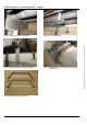
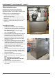
8. version stainlessAfter finish assembling of all
ball protection grids fix holding bracket with 3x
self-tapping screws on the reflector.
9. Push on protection grid burner top from behind
over ball protection grid and burner up to the
suspension bracket. Note that the lower short
bending is on the left side in view from behind.
Fix burner protection grid burner top with
supplied cable straps or similar at bottom
protection grid.
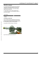
10. Protection grid burner top has to be cut holes
depends on installation on-site for flue system
and may be gas line. Connect flue system pipes
and gas line.
NOTE: Select the cutouts large enough to
compensate the thermal length expansion of
the heater!
11. Insert front protection cover burner between
front cover plate reflector and burner unit and fix
it with supplied cable straps or similar on
protection grid burner top (Fig. 39, page 36).
12. Protection grid burner end side has to be cut
hole depends on installation on-site for gas line.
Fix with supplied cable straps or similar on
protection grid burner top.
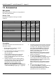
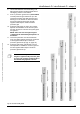
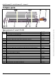
Please note the required number and
length of segments ball protection grids
for each type of heater. Compare this to
the tabular and graphical overview.
Fig. 34: Overview of ball guards