
Operating instructions


infraSchwank D / calorSchwank D - shape U
31
Version 005 infra_calor D shape U Australia 42/14 Technical specification subject to change
Adjusting thermal load
for modulating operation
Adjusting the nozzle pressure
1. Open first the gas cock which is at the end of the
flexible gas hose (Fig.28, page 30).
2. Open the test nipple connection pressure.
Connect the pressure measuring instrument to the
test nipple and determine the connection
pressure.
Close the test nipple after the measurement!
3. Open the test nipple nozzle pressure.
Connect the pressure measuring instrument to the
test nipple to determine the nozzle pressure.
4. The required nozzle pressure for natural gas H
(W
o,B
=50.0 MJ/m
3
) or propane is shown in table
5, page 18.
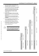
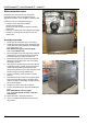
4. Take off the plastic cap A (see Fig. 31, page 31)
from the lifting magnet.
5. Put the radiant tube into operation
In case a different value has to be set the output current
value in the Modulation Box has to be changed.
Please follow below mentioned procedure
[e.g. 0.87 / 0.6 kPa]:
7. Switch the jumper at the ThermoControl Plus M to
“Modulation”
8. Switch on the “Chimney sweeper” mode at the
ThermoControl Plus M
9. Ensure that the input pressure at the gas pressure
regulator is sufficient enough [e.g. 1.13kPa]
10. Push the “+/-“ button (button block “B”) so that the
measured nozzle pressure will be 0.1 kPa below the
required minimum value (e.g. 0.5 kPa).
If the value cannot be adjusted, the mechanical
limitation at the lifting magnet (large adjusting
screw B, Fig. 31) needs to be amended.
Afterwards continue with adjusting to the required
minimum value
11. To adjust the maximum pressure, the jumper has to
be switched to “Max”. With the “+/-“ buttons adjust
the value to 0.1 kPa above the required maximum
pressure (e.g. 0.88 kPa). In case the value cannot
be adjusted the mechanical limitation of the lifting
magnet (small adjusting screw C, Fig. 31) needs to
be amended. Afterwards continue with adjusting to
the required minimum value.
12. Check the minimum value again and re-switch the
jumper to “Min” position and adjust the value if
necessary (e.g. 0.5 kPa).
13. Adjustment of the mechanical pressure range of
the lifting magnet:
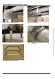
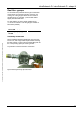
Place the jumper of the Modulation Box to the
“N” position. “Chimney sweeper” mode needs to
be still switched on. Disconnect the power
supply (clamp 7 / 8, Fig. 32) of the Modulation
Box or the connector of the lifting magnet.
Adjust the minimum value to the required nozzle
pressure (e.g. 0.6 kPa) at the lifting magnet.
Re-connect the electrical connection at the
Modulation Box (clamp 7 / 8) or the connector of
the lifting magnet and adjust the required
maximum value (e.g. 0.87 kPa) at the lifting
magnet.
14. Switch off the “chimney sweeper” mode.
15. Close test nipple after the measurement and and
check if the test nipple is gas-tight.
16. Put the plastic cap A on the lifting magnet
Fig. 31: Section of modulating lifting magnet
Fig. 32: Modulation Box