
Operating instructions


infraSchwank D / calorSchwank D - shape U
30
Version 00
5
infra
calor D shape U Australia
42/14
Technical specification subject to change
Adjusting nominal thermal load
at two-stage operation
Adjusting the nozzle pressure
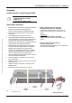
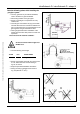
1. Open first the gas cock at the end of the flexible
gas hose (Fig.28, page 30).
2. Open the test nipple connection pressure.
Connect the pressure measuring instrument to the
test nipple and determine the connection
pressure.
Close the test nipple after the measurement!
3. Open the test nipple nozzle pressure.
Connect the pressure measuring instrument to the
test nipple to determine the nozzle pressure.
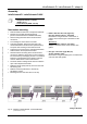
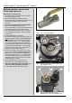
4. Take off the plastic cap E (see Fig. 30, page 30)
from the lifting magnet (lift the cap with a small
screw-driver)
5. Put the radiant tube into operation.
7. The electrical supply must activate for burner unit
and lifting magnet to adjust the nozzle pressure
of max. load. Turn the outer adjusting screw C
(width 8) slowly in the “+” or “-” -direction while
continuously watching the pressure measuring
instrument. Stop turning as soon as the required
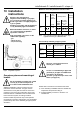
nozzle pressure is reached The required nozzle
pressure for natural gas H (W
o,B
=50.0 MJ/m
3
) or
propane is shown in table 5 page 18.
8. The electrical supply must activate only for the
burner unit to adjust the nozzle pressure of min.
load. Turn the inner adjusting screw D (screw-
driver 6x1) slowly in the “+” or “-” -direction while
continuously watching the pressure measuring
instrument. Stop turning as soon as the required
nozzle pressure is reached.
9. Checking adjustment nozzle pressure as
described by the single stage performance.
10. Close test nipple after the measurement and
and check if the test nipple is gas-tight.
11. Put the plastic cap E on the lifting magnet.
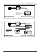
Fig 28: Gas cock with integrated TSD
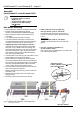
Fig 29: Adjusting screw nozzle pressure single stage
gas combination valve
Fig 30: Adjusting screw nozzle pressure with
lifting magnet two stage gas combination valve
A
B
E
D
C