
Operating instructions


infraSchwank D / calorSchwank D - shape U
26
V
ersion 005
in
fra calor D shape U Australia 4
2
/14
Technical specification subject to change
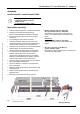
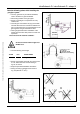
Gas connection has to be positioned in
the axle of the heater. Otherwise
torsional forces will operate on the hose!
Avoid twisting of the flexible hose!
(When tightening the union, counter hold
the nipple on the hose.)
Pay attention that the flexible hose will
not be mechanically damaged by tools
etc. Do not buckle the hose.
Do not mount damaged flexible hoses!
Damaged hoses can break due to the
movement of the heater.
Electrical installation
(wiring diagram)
Danger of electric shock!
Electric shocks are highly dangerous!
Working at the electrical equipment of
the appliance is only allowed by
professional personnel observing the
current IEE regulations.
Isolate the electrical supply while
working at the electrical equipment of the
appliance and safeguard the appliance
against unintentional connection to the
circuit.
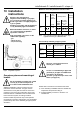
The gas supply and electrical cable must
be situated on the outside of the
radiation and combustion heat. Only use
heat-resistant cables near the tubes.
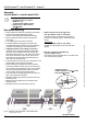
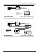
Electrical connection
Single stage operation
Route the connection cable (power supply) to the
three-pin plug and connect the cables
(see Fig. 24, page 27).
Plug in the three-pin plug into the socket of the
burner box.
Connect the plug of the fan into the corresponding
socket at the burner box.
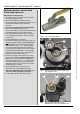
Pay attention of the correct polarity! If the
polarity is incorrect, the firing device will
not note any ionisation signal!
You find the three-pin socket for the
electrical supply on the burner box.
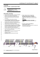
Electrical connection
two stage operation
Route the connection cable (power supply burner
unit) to the three-pin plug and connect the cables
(see Fig. 25, page 27).
The connection cable of the modulation spool
connects by a branch box (see Fig.25, page 27).
Plug in the three-pin plug into the socket of the
burner box.
Connect the plug of the fan into the corresponding
socket at the burner box.
Start and ignition of the heater has
always to be in full load. After a time of
minimal 1 minute the heater can be
switched to small step.
You find the three-pin socket for the
electrical supply on the burner box. The
connection cable of the modulation spool
is screw on the gas combination valve.
Electrical connection
modulating operation
Make sure that protective earth is connected
between modulation box and ThermoControl Plus M
controller.
Route the connection cable (power supply burner
unit) from the modulation box to the three-pin plug
and connect the cables (see Fig. 26, page 28).
Connect the connection cable for the lifting magnet
from the modulation box direct to the lifting magnet
modulating valve (see Fig.26, page 28).
Plug in the three-pin plug into the socket of the
burner unit.
Connect the plug of the fan into the corresponding
socket at the burner unit.
Start and ignition of the heater has
always to be in full load. After a time of
minimal 1 minute the heater can be
switched to small step.
You find the three-pin socket for the
electrical supply on the burner unit. The
connection cable of the lifting magnet is
screws on the modulating gas
combination valve.