055AC/RC HANDBOOK SITE PLANNING GUIDE INSTALLATION GUIDE OPERATION AND MAINTENENCE MANUAL SCHREIBER ENGINEERING CORPORATION CERRITOS, CA
OVERVIEW The Schreiber 1055 chiller is designed to provide constant chilled water to an Intera MR system. It is built for outdoor or indoor installation. The chiller is completely self contained and includes 2 pumps, 2 5 ton refrigeration modules, condenser and fans, and a chilled water reservoir. The modular construction allows for quick and easy service. The microprocessor control and remote terminal allow for operation of the chiller at the chiller and from a remote location.
and the outer layer is powder coated steel. There is 1” of foam in between the layers. A 1” overflow (vent), sight glass, and 1” fill fitting is installed on the main access side of the chiller. There is also a 1⁄2” drain. Since the reservoir is vented to atmosphere, a backflow kit is provided to prevent water from flowing out of overhead pipes and overflowing the reservoir. A water supply and hose should be plumbed to the chiller for filling.
WEIGHTS Chiller (Dry, reservoir holds 60 Gallons) Condenser 1050 525 HVAC Requirements: If the condenser is installed indoors, adequate fresh air must be brought into the space and exhausted. If the chiller section only is installed indoors, a small amount of heat is added to the space and should be accounted for in HVAC load calculations.
CryoCompressor 1⁄2” FPT Heat 1” FPT Exchangers 1.5 GPM 16 GPM 1⁄2” 1” *Based on a total piping length of 300’ per loop. Only use copper or PVC (schedule 80) piping. All piping should be insulated to prevent condensation and to minimize heat gain from the ambient air. A maximum of 30% by volume of Ethylene Glycol can be added to the system. The glycol should be added directly to the reservoir through the fill port.
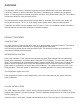
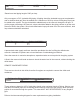
Reservoir Drain 4 3 REV TITLE DESCRIPTION 2 REVISIONS DATE REVISED 1 APPROVED A B C D 1⁄2" Shutoff valve provided inside chiller 8 7 NOTES: Pressurized water line with shutoff valve must be provided at the chiller site. The chilled water reservoir is filled directly through the fill port, and not through the supply or return lines. A pressurized water supply with a shutoff valve and hose are all that is required. 6 Tank Fill 5 4 3 PHILIPS INTERCONNECT 2 PHILIPS PIPING INTERCONNECT.
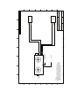
A B C D E F G H 8 2 7 7 2 Hot Gas Connections 1 6 2 6 2 Hot Gas Connections 1 5 Chiller End View All connections are 1⁄2" Liquid Connections 1 4 4 Schrader Valves (field installed) Liquid Lines- 5/8" 25' or more of rise requires a trap at the base and one along the mid point of the rise (Ex.
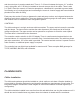
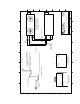
A B C D E F G H 8 8 DRAIN 1⁄2" FPT SIGHT GLASS FILL PORT 1" MPT OVERFLOW 1" MPT 7 7 6 Chilled Water Reservoir 65 gallon capacity 6 Shutoff Shutoff 5 Cryo-Compressor Pump GCHE/GAHE PUMP Evaporator 2 and Isolation Valve Evaporator 1 and Isolation Valve 5 4 Pressure Relief Bypass Bypass Valve Backflow Solenoid Valve (NC) Check Valve Strainer 4 REV Strainer Clean Out 1⁄2" FPT 3 DESCRIPTION 2 REVISIONS 2 1055_REFRIGERATION_SK ID.
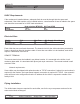
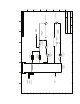
REV. DESCRIPTIONS D ATE BY 74.000 34.188 58.250 Minimum Clearances: Rear: 3 ft (Drain and Sight Glass) Front : 4ft (Control Box) Right: 4 ft (Condenser Side) Top: 12 ft (Fan Exhaust) Note: No clearance requirements for top and right side for remote air cooled and water cooled models. Refrigration piping connections for remote condensers are from the front panel of the chiller. UNLESS OT HERWISE SPE CIFIED DIMENSIONS A RE IN INCHES TOL ERAN CE A RE: FRAC TION DE CIMALS ANG LES + .XX +.03 +. 5 .XXX + .
REV. D ATE BY 81.060 35.974 19.013 30.000 .500 DESCRIPTIONS 74.000 2.000 FILL PORT (1" MPT) 8.846 21.093 4.465 CLEA N OUT 3/8" NPT PUMP 1 RETU RN PRESSURE GAUGE PUMP 1 DISCHARGE (1" FP T) GCHE/GAHE PUMP STATU S L IGHTS 33.500 PUMP 2 RETU RN (1/2 " FPT ) PUMP 2 DISCHARGE PRES SURE GAUGE PUMP 2 DISCHARGE (1/2 " FPT ) Cryo -Comp P ump MAIN CONT ROLLER 33.031 27.531 22.031 30.120 42.654 32.295 29.750 21.500 13.093 VFD E NCLOSURE PUMP 1 DISCHARGE PRESSURE GAUGE QUICK DISCONNECT 61.
1055 Startup Initial Startup Procedure INSTALLATION INSPECTION Visually inspect the chilled water piping system. There should be two pipe loops; 1” and 1⁄2”. The piping should be copper or PVC. Verify that all connections are made and that all required valves are open. Verify that the main breaker or disconnect is on (disconnect for branch circuit to the chiller, not the chiller disconnect), and check the fuse or breaker size. Compare with the installation requirements.
Initial Power Up NOTE: for the checkout procedure, it may be more convenient to use the remote terminal. It can be removed from the wall bracket and unplugged, and plugged into the chiller with another short length of telephone cable. All procedures are described using the terminal shortcut keys, but can be accessed through the menu on the built in display of the controller. See the controller operation section for more detail.
The compressor is also extremely noisy when running backwards. In general, an experienced technician will not have to look at the gauges. Fans The fans should be spinning CLOCKWISE if looking down on the fan. Air should be drawn for the bottom of the chiller and be discharged out of the top. SYSTEM STARTUP Pump 2 (cryo compressor pump) Startup and bypass adjustment. • Go to the ON/OFF screen. • Turn on PUMP 1.
System 1: Verify that pump 1 is on. Compressor 1 and compressor 2 should be off. Check the units (C or F, psi or bar). Change the units to whatever system is required. They should be changed before permanent settings are made, because they only change the display of sensor values, not setpoint values. For example, if the reservoir is at 68 F, and the setpoint is 50 F, changing the units to C will change the reservoir temperature display to 20 C, but the setpoint will be 50 C, not 10 C.
OPERATION OVERVIEW OF OPERATING SEQUENCE: During normal operation, both pumps will run continuously. The cryo-cooler pump continuously draws water from the reservoir, pumps it to the cryo compressor, and back to the chilled water reservoir. The GCHE pump does the same, except that the water runs through the two refrigeration system evaporators before returning to the reservoir.
Cryo Compressor Pump The pump cryo compressor pump is a positive displacement pump capable of delivering 4 GPM. This flow rate is constant under all conditions. The discharge pressure will vary according to the length of pipe and the number of fittings in the pipe system. A T-handle pressure relief valve allows adjustment of the discharge pressure. It should be set to no more than 50 psi. The cryo compressor pump motor is EXTERNALLY overload protected.
allows the chiller to run, but water must be added immediately. Since the reservoir is open to the atmosphere, a small amount of water may be lost due to evaporation. The local weather conditions will dictate how often the reservoir should be topped off. If water needs to be added more than once a month, there is a possibility of a leak in the system. Flow Switch There is a flow switch on each piping loop to protect the chilled water system.
Each refrigeration system is mounted on a galvanized steel skid, and is completely self contained. It contains the following: High Pressure Switch The high pressure switch is a manually resetting, totally encapsulated switch that is mounted on a Schrader valve connection. If the switch requires replacement it can be unscrewed from the piping system without loss of refrigerant. In the event of a high pressure switch failure, the switch must be manually reset by pressing the red button.
Pressure Transducer The pressure transducer reads the head pressure of the system and transmits this value to the controller. The controller uses this value to determine the proper fan speed. It is installed on a Schrader valve connection allowing it to be removed without a loss of refrigerant. Liquid Line/ Suction Line Heat Exchanger This heat exchanger subcools the liquid leaving the receiver and superheats the gas leaving the evaporator.
Compressor The compressor is a high efficiency compliant scroll compressor. It is hooked to the refrigeration system with rotor lock valves. The rotor lock valves contain a double seating shut off valve and an access port. The valve is shipped from the factory in the fully open (back seated) position and should remain in this position during normal operation. Crankcase heaters are installed on the compressors and are always energized.
Controller Quick Reference Guide: This section describes some of the common functions performed in the controller. Basic Navigation MAIN MENU Use the UP and DOWN arrow keys to scroll through the available menus. The currently selected menu will appear in all capital letters with an arrow next to it. Press the ENTER key to go into that menu. INSIDE A MENU LOOP Use the UP and DOWN arrow keys to scroll through the screens in a menu. When at a screen, the cursor is in the upper left hand corner.
Basic Tasks Enabling/Disabling pumps and compressors: At the chiller: 1. 2. 3. 4. Press the PRG key Scroll down to the CURRENT STATUS Screen and press enter. The screen will change to the RUNNING STATUS screen. Press the UP arrow key once to go to the SYSTEM ON/OFF screen. 5. Press the ENTER key to move the cursor to the different devices. Use the UP or DOWN arrow keys to turn each device off or on. At the terminal 1. Press the ON/OFF key. 2.
Checking Alarm History At the chiller 1. 2. 3. 4. Press the PRG key. Scroll down to the ALARM HISTORY menu and press ENTER. Use the UP arrow to review past alarms. To clear the alarm history, press the UP and DOWN arrow keys simultaneously for 5 seconds.
Controller Operation The 1055 can be controlled from 2 locations; the built-in display on the controller (located inside the main chiller enclosure) and from the remote mounted terminal. All control functions can be performed at both locations; however, there are more buttons on the remote terminal that allows faster access to various menu functions.
MENU TREE The diagram below shows the hierarchy of the controller menus. Menus shown in gray are password protected.
Chiller menu descriptions Key name in parentheses denotes the shortcut key for accessing that screen directly. MAIN MENU (MENU or PROG) CURRENT STATUS (BLUE key) RUNNING STATUS Shows the current on or off status of the system pumps and compressors. LOOP STATUS Displays the current discharge temperature and return temperature for each pump loop. COMPRESSOR STATUS Displays the head pressure and suction pressure for each refrigeration circuit. Suction pressure display is optional.
Sets and displays the main temperature setpoints. DISCHARGE SETPOINT DISCHARGE: The setpoint for the chilled water reservoir. This temperature will be delivered through both pump loops. HIST: This is the differential around the setpoint of which the system will cycle. HIST = Histeresis. A 50 F setpoint with a 1.0F differential means the system will turn on at 51 F and shut off at 49 F.
automatically choose the correct rotation sequence, either forward or reverse. RUN HOURS (MAINTENCE key) Displays the run hours for each compressor, pump and fan. FACTORY SETTINGS- Password Protected These parameters are discussed in the special maintenance section of the manual. ALARM HISTORY Displays the last 25 alarms. Use the UP key to scroll through each alarm. Every alarm is time and date stamped. Pressing the UP and DOWN arrows simultaneously will reset the alarm history.
DELAY: A filter on the input to prevent nuisance trips. MANUAL CONTROL (INPUT/OUTPUT key, password protected) Allows the inputs and outputs to be bypassed around the control system and manually set to specific values. This is used for service and test purposes only. The special maintenance section describes the functions of manual control.
1055 Maintenance This section describes routine maintenance functions that need to be performed periodically. Chilled Water System Glycol Solution Concentration and Level • A warning alarm will be generated when the reservoir level becomes too low. Filling with water will clear the alarm. By reviewing the alarm history, the rate of water loss can be determined by checking the time between subsequent water level alarms. The water level should be inspected by a time in between those alarms.
1055 SERVICE NOTE: This section is for qualified service personnel only. Procedures outlined in this section of the manual can cause personal injury or permanent damage to the chiller and the equipment it is cooling. If you have any questions about the procedures outlined in this section please contact Schreiber Engineering directly. Refrigeration System The 1055 is made up of two separate refrigeration system, the only shared components is the condenser and it’s fans.
3. Stop the compressor when the suction pressure is just above vacuum. 4. Disable the compressor. Compressor Removal 1. 2. 3. 4. 5. 6. Pump down system to be replaced. Close suction and discharge valves. Evacuate remaining refrigerant out of the compressor. Shut down compressor system. Turn off main disconnect. Remove crankcase heater leads, and compressor power leads from the contactor. Record color sequence of leads. 7. Turn on disconnect. 8. Remove leads from the compressor motor adapter. 9.
fan speed. The band is the value around the setpoint of which controls the speed signal. If the head pressure is below the setpoint by the value of the band or more, the controller sends the minimum output of 0 volts DC. If the head pressure is greater than the setpoint by the value of the band or more, the controller sends the max output; 10 VDC. If the head pressure falls between the setpoint value plus or minus the band, the speed is adjusted accordingly.
The range around the setpoint in which the fans run at partial speed. Above the band the fans are full speed, below the band the fans are off. Condenser Fans Service Procedures Transducer Replacement 1. 2. 3. 4. 5. Disable Variable Speed operation Unplug the signal cable from the faulty sensor, Unscrew the sensor. Replace with new sensor and reconnect cable. Enable Variable Speed operation VFD Bypassing.
8 7 6 5 4 3 2 1 24VAC Black J9 J11 J12 NC8 C7 J14 C8 NO8 C7 J13 NO7 NO6 C4 C4 NO5 NO4 C1 N03 C1 N01 Rx+/Tx+ GND Rx-/Tx- 24VAC Red Fan Relay NO2 Controller H H J15 J10 14 c 11 7 G FUSE 5X20 J3 J4 J5 ID1 ID2 ID3 ID4 ID5 ID6 ID7 ID8 IDC1 G FR1 J2 VG VG0 Y1 Y2 Y3 Y4 J1 B4 BC4 B5 BC5 1 B1 B2 B3 GND +VDC G G0 2 Circular Connectors F F Aux Wire Pass Through CC1 CC2 Backflow Kit Terminal Block E c E BFTB Transformer D D Disconnect Wire Duct A1 C
5 4 REV VFD Detail 3 TITLE DESCRIPTION 2 REVISIONS DATE REVISED 1 4/8/2003 APPROVED H A B C D E 4 3 T3 L3 2 1055_TERMINAL_WIRING.
Non Fused GCHE Pump C1 Compressor 1 P2 4 4 C2 Compressor 2 Crankcase Heater 3 3 REV TITLE VFD REVISIONS Fan Motors 5A DESCRIPTION 2 DATE REVISED 1 4/8/2003 APPROVED D E F G H A 7 6 5 Cryo Cooler Pump 2 1055_TERMINAL_WIRING.
A B C D E F 8 B1 7 Circuit1 Pressure CC2-7 B2 B3 Circuit2 Pressure CC2-7 GND 6 Discharge Temp CC2-7 CC2-7 ANALOG INPUTS VDC 6 5 BC5 B5 BC4 5 Return Temp Pump 1 Return Temp Pump 2 B4 G 7 4 From 24VAC Black 4 REV ANALOG INPUTS 3 3 VG0 H 8 Y1 VG REVISIONS 2 DATE REVISED 1 JEFF JOHNSON DRAWN BY 1 DATE APPROVED 4/8/2003 4/4/2003 Analog Input/Output Wiring 1055_TERMINAL_WIRING 1055_TERMINAL_WIRING.
Controller NO1 11 F1 14 CC1-11 A1 2 P1 CC1-14 4 3 REV TITLE DESCRIPTION 2 REVISIONS DATE REVISED 1 APPROVED A B C D E F 8 C4 C2 C1 VFD-12V NO8 NO5 NO4 NO3 NO2 7 6 CC2-7 A1 A1 A1 A2 A2 A2 5 VFD-FWD F1 7 LL2 C2 BF2 P2 LL1 C1 BF1 A2 CC2-14 4 VFD Start Signal ALARM Lamp Fan Relay Liquid Line Solenoid Compressor 2 Pilot Lamp Backflow Kit Valve Cryo Compressor Pump Pilot Lamp Liquid Line Solenoid Compressor 1 Pilot Lamp Backflow Kit Valve GCHE Pu
A B C D E F G H 8 8 7 24VAC Red c CC2-7 CC2-2 CC1-7 CC1-2 24VAC Black 6 6 REMOTE ON/OFF (OPTIONAL) FIELD INSTALLED Float FS2 FS1 LP2 HP2 LP1 HP1 G0 G 5 CC2-3 CC2-1 CC1-3 CC1-1 5 4 4 ID3 7 3 REV 3 IDC1 ID8 ID7 ID5 ID6 ID4 ID2 ID1 TITLE REVISIONS 2 DATE REVISED 1 JEFF JOHNSON DRAWN BY 1 DATE APPROVED 4/8/2003 4/4/2003 DIGITAL INPUT WIRING 1055_TERMINAL_WIRING 1055_TERMINAL_WIRING.