
Schonstedt Instruction Manual


15
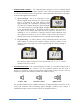
Automatic and Manual Output Power
The Rex transmitter delivers power to the "load" that it is connected to. In the
conductive mode, the load is the circuit formed by the cable or pipe being traced,
the soil return, and the ground stake. In the inductive clamp and inductive modes,
the loads are the clamp and the antenna, respectively. The inductive clamp and
inductive modes require the maximum power that the transmitter can deliver.
Therefore, the transmitter automatically operates at maximum power output, and
there is no need for manual power adjustment.
In the conductive mode, the power delivered to the load is highly dependent on the
external elements (soil, type of conductor, stake placement, etc.). In some cases,
more power is desired to achieve more distance or depth; in other cases, less power
is desired to avoid bleeding to nearby conductors. Therefore, while in the conductive
mode, the user has the ability to adjust the output power manually, using the front
panel controls and visual indicators described further down in this manual.
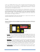
Transmitter Current Measurement
When operating in the conductive mode, the Rex transmitter displays the amount of
current flowing into the utility being traced. This is very useful in determining how good
of a circuit has been established by the operator. The circuit can be improved by
relocating the ground stake or improving the metal to metal contact of the
conductive clips. A low current reading indicates a poor trace conductor, poor soil
conductivity, or poor ground stake contact/placement. Higher current readings
indicate a better circuit and a better chance at tracing long distances and deep
conductors.
If the current reading is low, try improving the connection to see if the current
increases (check the cables, clips, and ground stake; wet the ground; clean rust or
dirt; etc.). Often, the reason for the low current is the soil itself (sandy or very dry)
and/or the conductive quality and integrity of the pipe or cable that is being traced
(cast iron pipes, rusted or broken wires, heavy insulation to ground, etc.). If an
improved connection cannot be made, there may be a small amount of current still
circulating in the circuit. Try increasing the output power manually and/or increase
the gain on the receiver.
Line Voltage and Impedance Measurement
When the transmitter is operating in conductive mode and a new frequency is
entered, it performs an automatic measurement of the AC and DC voltages that are
present on the line to be traced. If the voltage measured on the line is below 5 volts
(DC or AC), then the measurement is transparent to the user and the transmitter
proceeds to transmit the desired signal onto the line. If the voltage is above 5 V (DC