
Installation Manual

Inverter/Charger Installation
975-0637-01-01 Rev E 1–27
This guide for use by qualified personnel only
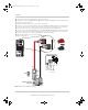
Step 6: Performing Checks Prior to Initial Start-Up
Before testing your installation, ensure these conditions are met.
❐ DC disconnect switch or breaker is turned off.
❐ AC input and output breakers are turned off.
❐ AC earth are properly installed.
❐ AC input connections and AC output connections are wired correctly on the
terminal block and not reversed.
❐ Positive (+) battery cable is connected to the positive (+) battery terminal
through the DC fuse and disconnect switch or DC circuit breaker.
❐ Negative (–) battery cable is connected to the negative (–) battery terminal.
❐ Battery voltage is within the proper range for this unit: 21–33 VDC for 24-volt
models and 42–66 VDC for the 48-volt model.
❐ All connections are tight.
Step 7: Testing Your Installation
There are several tests to be performed for testing your installation. These tests
will verify that:
• The Conext SW works in invert mode.
• The Conext SW works in charge mode.
• The Conext SW works in AC bypass mode.
If the test fails at any point, go to “Step 6: Performing Checks Prior to Initial Start-
Up” on page 1–27 and go through the checklist again to check the installation.
Then perform the test again. If the test fails again, see the troubleshooting
section in the Conext SW Inverter/Charger Owner’s Guide.
WARNING
ELECTRICAL SHOCK HAZARD
The Inv Enable button on the Conext SW front panel and the SCP do not
disconnect DC or AC input power to the Conext SW. Open and lockout the
disconnect switches or breakers at all AC and DC sources. Test with a
multimeter before tightening electrical connections.
Failure to follow these instructions can result in death or serious injury.
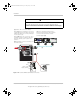
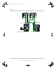
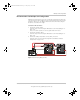
Figure 1-13 Conext SW Front Panel
ConextSWEUROInstallationGuide.book Page 27 Tuesday, July 21, 2015 4:22 PM