
Installation Manual

Installation
1–24 975-0637-01-01 Rev E
This guide for use by qualified personnel only
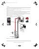
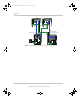
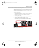
Figure 1-11 Conext SW DC Connections
Battery
Negative
Battery
Positive
Xanbus Stacking REM BTS
connect to
BTS port
Battery or Battery
Enclosure
(2)(a)
(2)(b)
(1)
Route the DC cables from the battery bank to the inverter/charger.
(2) Install a DC disconnect switch (a) and DC fuse (b) or a DC circuit breaker (c) between the inverter/charger and
the battery on the positive terminal.
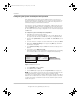
(3) Open and lockout the DC disconnect switch or DC circuit breaker.
(4) Connect one connector on the POSITIVE (+) cable to the BATTERY POSITIVE terminal on the inverter/charger.
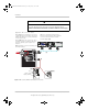
Connect in the order shown on Terminal Connection below. If the bolt has a nut and washer, remove them first.
(5) Connect the other connector to the battery fuse or DC circuit breaker on the POSITIVE (+) line.
(6) Connect one connector on the NEGATIVE (–) cable to the BATTERY NEGATIVE terminal on the inverter/charger.
Connect in the order shown on Terminal Connection below. If the bolt has a nut and washer, remove them first.
(7) Connect the other end of the cable to the NEGATIVE (–) terminal on the battery.
(8) Attach the DC terminal covers to the inverter/charger
using the screws provided.
(2)(c)
(4)
(6)
(7)
(8)
Nut
Washer
Connector
Battery Terminal on
the inverter
Ter m ina l Co nne cti on
or
(5)
ConextSWEUROInstallationGuide.book Page 24 Tuesday, July 21, 2015 4:22 PM