
Installation Manual


Inverter/Charger Installation
975-0637-01-01 Rev E 1–21
This guide for use by qualified personnel only
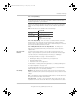
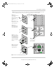
Figure 1-10 Conext SW AC INPUT and OUTPUT Connections
L
N
AC Cable
(3)
(4)
(1)
Make the wiring connections to the AC
source main panel.
(2) Route the AC cable to the inverter/
charger.
(3) Remove the wiring compartment cover
panel on the inverter/charger.
(4) Remove the AC knockouts from the side
or bottom (or both). Do not leave the
knockout inside the wiring compartment.
(5) Install strain-relief clamps in the AC
knockouts.
(6) Route the AC input cable through the AC
input knockouts and inside the wiring
compartment.
(7) Connect Line to L, Neutral to N,
earth to on the AC input terminals. If solid
ground wire is being used, the wire can be
connected directly under the screw heads. If
stranded ground wire is being used, ring
terminals must be used.
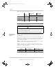
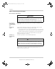
(8) Tighten the terminal screws. Leave a
service loop in the wires inside the wiring
box.
(9) Route the AC output cable through the
AC output knockouts and inside the wiring
compartment.
(10) Connect Line to L,
Neutral to N,
earth to on the AC output
terminals. If solid ground
wire is being used, the wire
can be connected directly
under the screw heads. If
stranded ground wire is
being used, ring terminals
must be used.
side AC
knockouts
bottom AC
knockouts
to Inverter
AC INPUT
strip at least
50mm
strip at least
13mm
Inverter Load Panel
AC Source
Main Panel
(12)
(1)
(2)
Transfer switch
(11) Tighten the terminal
screws. Leave a service
loop in the wires inside the
wiring box.
(12) Make the wiring
connections to the inverter
load panel.
(13) Replace the wiring
compartment cover panel
on the inverter/charger.
ConextSWEUROInstallationGuide.book Page 21 Tuesday, July 21, 2015 4:22 PM