
Installation Instructions

INSTALLATION INSTRUCTIONS
GLASS TOUCH PANEL
REFERENCE:
LSSMBU02N* LSSMTH08N*
LSSMBU03N*
LSSMBU04N*
LSSMDN01N*
LSSMBU06N*
LSSMDP01N*
LSSMBU09N*
LSSMBU10N*
LSSMKH03N*
LSSMBU12N*
LSSMKH03R*
LSSMTH07N*
* : P_A=Product, S_A = Mock-up Sampled
REFERENCE DESCRIPTION
LSSMBU02N*
GLASS PANEL, MODUS,
2 BUTTONS
LSSMBU03N*
GLASS PANEL, MODUS,
3 BUTTONS
LSSMBU04N*
GLASS PANEL, MODUS,
4 BUTTONS
LSSMBU06N*
GLASS PANEL, MODUS,
6 BUTTONS
REFERENCE DESCRIPTION
LSSMBU09N* GLASS PANEL, MODUS,9 BUTTONS
LSSMBU10N*
GLASS PANEL, MODUS,
10 BUTTONS
LSSMBU12N*
GLASS PANEL, MODUS,
12 BUTTONS
LSSMKH03N*
GLASS KEYCARD
HOLDER, MODBUS
LSSMKH03R*
GLASS KEYCARD
HOLDER, MODBUS,
RFID
LSSMDN01N*
GLASS DOOR PANEL,
MODBUS,
NUMBER
LSSMDP01N*
GLASS DOOR PANEL,
MODBUS, NUMBER,
PRESENCE
REFERENCE DESCRIPTION
LSSMTH07N*
GLASS THERMOSTAT,
MODBUS, 7 BUTTONS
LSSMTH08N* GLASS THERMOSTAT, MODBUS, 8 BUTTONS
Category Reference Description
Glass Touch Panels LSSMBU02N*
GLASS PANEL, MODBUS,
2 BUTTONS
Glass Touch Panels LSSMBU03N*
GLASS PANEL, MODBUS,
3 BUTTONS
Glass Touch Panels LSSMBU04N*
GLASS PANEL, MODBUS,
4 BUTTONS
Glass Touch Panels LSSMBU06N*
GLASS PANEL, MODBUS,
6 BUTTONS
Glass Touch Panels LSSMBU09N*
GLASS PANEL, MODBUS,
9 BUTTONS
Glass Touch Panels LSSMBU10N*
GLASS PANEL, MODBUS,
10 BUTTONS
Glass Touch Panels LSSMBU12N*
GLASS PANEL, MODBUS,
12 BUTTONS
Glass Touch Thermostat LSSMTH07N*
GLASS THERMOSTAT, MODBUS,
7 BUTTONS
Glass Touch Thermostat LSSMTH08N*
GLASS THERMOSTAT, MODBUS,
8 BUTTONS
Glass Door Panels LSSMDN01N*
GLASS DOOR PANEL, MODBUS,
NUMBER
Glass Door Panels LSSMDP01N*
GLASS DOOR PANEL, MODBUS,
NUMBER, PRESENCE
Glass Keycard Holders LSSMKH03N*
GLASS KEYCARD HOLDER,
MODBUS
Glass Keycard Holders LSSMKH03R*
GLASS KEYCARD HOLDER,
MODBUS, RFID
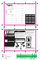
Dimensions
Dimension
95 x 95
LSSMBU02N*, LSSMBU03N*,
LSSMBU04N*, LSSMBU06N*,
LSSMBU09N*, LSSMBU12N*,
LSSMTH07N*, LSSMDN01N*,
LSSMKH03N*, LSSMKH 03R*
160 x 95
LSSMBU10N*, LSSMTH08N*
160 x 120 LSSMDP01N*
Front cover options
Glass surface with customizable background color
(Typical colours --- silver, champagne gold, white and black)
Supply voltage 24 V DC
Current consumption 30 mA
Physical interface RS485
Communication protocols Modbus
RFID Frequency 13.56 MHz
Temperature tolerance ± 0.5° C / ±0.9° F
Indicator backlight
Typically available as follows, and customisable:
Black glass: Available colours: white, amber, blue, light green, red
White glass: Available colours: black, grey, amber, blue, red
Silver glass: Available colours: black, white, amber, blue, red
Gold glass: Available colours: black, white, red
Mounting Snap-in magnetic mounting
Warm up time Typical 20 seconds
Operating temperature 0 to 45° C / 32° to 113° F
Storage temperature 0 to +60° C / 32 to 140° F
Operating humidity 10% - 95% RH, non-condensing
IP Class IP20
Features
Glass Touch Panel Hotel Series are extra low voltage switch panels
connected through the Hotel Room Controller system (HRC System).
They provide direct switching from inside a hotel room of lighting,
dimming, curtains and air conditioning.
Safety, Installation and Operation Requirements
DANGER
HAZARD OF ELECTRIC SHOCK, EXPLOSION OR ARC
FLASH
• This product must only be installed and serviced by
• Isolate the electrical supply before doing any work on this
product.
• Ensure that the product has been correctly installed and tested
for safe operation before reconnecting the electrical supply.
Failure to follow these instructions will result in death or
serious injury.
CAUTION
INSTALLATION HAZARD
Make sure that there is at least a depth of 35mm on a wall box for
the glass touch panel.
Failure to follow these instructions can result in injury or
equipment damage.
Installation Steps
Separate the mounting metal plate and wall box from the glass
touch panel.
Unscrew the 2x mounting screws from the mounting metal plate.
Install the wall box attached or use the wall box installed.
Screw the mounting metal plate to the installed wall box and pull
out the power wires (24 V/COM) and Modbus RS485 wires.
Connect the Modbus RS485 and power wires to the connectors
according to the connection diagram on the product.
Push the glass touch panel toward the mounting metal plate to
engage the side clips.
Wiring diagrams
LSSMKH03N*
LSSMKH03R*
LSSMBU02N*
LSSMBU03N*
LSSMBU04N*
LSSMBU06N*
LSSMBU09N*
LSSMBU12N*
LSSMTH07N*
LSSMDN01N*
LSSMBU10N*
LSSMTH08N*
LSSMDP01N*
GND
24VCC
RS485 A Line
RS485 B Line
RS485 A Line
RS485 B Line
24VCC
GND
TERMINATION DIAGRAM-RS485 VERSION FOR
TERMINATION DIAGRAM-RS485 VERSION FOR
Technical Support and Warranty
For technical or warranty queries, contact the Customer Care Centre in
your country:
www.schneider-electric.com/contact
2
3
4
QGH7885600Rev.01
1
2
3
4
5
diecut line
folded line
Dimension: 255 x 170 mm
85 x 85 mm (folded)
Colour: Black
Material: 80gsm paper
N U MBE R : Revision: Sheet:
D ECN
/
ECN
/
TCAN
REVD RND ESCR IPTION
QGH7885600
01
1
/
1
00
Sinda LIN
Initial Release, 2017/06/12DECN201716529
1
Mounting metal plate
Back plastic cover
If necessary, please insert a
small flat screwdriver between
the metal mounting plate and the
back plastic cover and give a
simple turn to detach them.
01
Sinda LIN
Updated CR and Remove “GCR_” &“_PTO”DECN2018
• The products are powered by the hotel customer control system
power module.The products must be working in the customer
control system.The products are input and display devices of
human-computer interaction .The products must be used with
HRC(Hotel Room Controller) of the customer control system.
Action
Pollution degree
Type 1
2