
User guide


PowerLogic™ PM5300 series user guide Chapter 6—Input / Output
© 2014 Schneider Electric All Rights Reserved 55
4. Move the cursor to point to the digital output you want to set up, then press Edit.
5. Move the cursor to point to the parameter you want to modify, then press Edit.
NOTE: If Edit is not displayed, it means the parameter is either read-only or can only
be modified through software.
6. Modify the parameter as required, then press OK.
7. Move the cursor to point to the next parameter you want to modify, press Edit,
make your changes, then press OK.
8. Press to exit. Press Yes to save your changes.
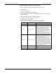
Digital output setup parameters available through the front panel
Parameter Values Description
Label -----
This can be modified only through software. Use this
field to change the default label and assign a
descriptive name to this digital output.
Control Mode
External, Demand Sync,
Alarm
This displays how the digital output functions.
• External: the digital output is controlled remotely
either through software or by a PLC using
commands sent through communications.
• Demand Sync: the digital output is associated
with one of the demand systems. The meter
sends a pulse to the digital output port at the end
of every demand interval.
• Alarm: the digital output is associated with the
alarm system. The meter sends a pulse to the
digital output port when the alarm is triggered.
Behavior Mode Normal, Timed, Coil Hold
• Normal: this applies when control mode is set to
External or Alarm. The digital output remains in
the ON state until an OFF command is sent by
the computer or PLC.
• Timed: the digital output remains ON for the
period defined by the On Time setup register.
• Coil Hold: this applies when control mode is set to
External or Alarm. For a unary alarm that is
associated with a digital output, you must set
Behavior Mode to Coil Hold. The output turns on
when the “energize” command is received and
turns off when the “coil hold release” command is
received. In the event of a control power loss, the
output remembers and returns to the state it was
in when control power was lost.
On Time (s) 0 to 9999 This defines the pulse width (ON time) in seconds.