
User manual


Table Of Contents
- NOTE: All page numbers are hyperlinks.
- Press Ctrl + - to go back.
- 870 USE 101 00 Version 3.0
- Contents
- Overview of TSX Momentum M1 Processor Adapters
- Overview of TSX Momentum Option Adapters
- Assembling TSX Momentum Components
- Assembling a CPU
- Overview
- Assembling a Processor Adapter and I/O Base
- Disassembling a Processor Adapter from an I/O Base
- Assembling a CPU with an Option Adapter
- Overview
- Assembling a Processor Adapter and an Option Adapter
- Mounting the Assembled Adapters on the I/O Base
- Disassembling a Module with an Option Adapter
- Installing Batteries in an Option Adapter
- Installation Guidelines
- Labeling the CPU
- Guidelines for Labeling the CPU
- Using the Modbus Ports
- Modbus Port 1
- Overview
- Modbus Port 1
- Cable Accessories for Modbus Port 1
- Pinouts for Modbus Port 1
- Modbus Port 2
- Overview
- Modbus Port 2
- Four-Wire Cabling Schemes for Modbus RS485 Networks
- Two-Wire Cabling Schemes for Modbus RS485 Networks
- Cable for Modbus RS485 Networks
- Connectors for Modbus RS485 Networks
- Terminating Devices for Modbus RS485 Networks
- Pinouts for Modbus RS485 Networks
- Using the Ethernet Port
- Using the I/OBus Port
- Using the Modbus Plus Ports
- Configuring an M1 CPU with Modsoft
- Configuring the Processor Adapter
- Overview
- Selecting an M1 Processor Adapter
- Specifying an M1 Processor Type
- Default Configuration Parameters
- Changing the Range of Discrete and Register References
- Changing the Size of Your Application Logic Space
- Changing the Number of Segments
- Changing the Size of the I/O Map
- Establishing Configuration Extension Memory
- Configuring Option Adapter Features
- Overview
- Reserving and Monitoring a Battery Coil
- Setting up the Time-of-Day Clock
- Setting the Time
- Reading the Time-of-Day Clock
- Modifying Communication Port Parameters
- Overview
- Accessing the Port Editor Screen
- Parameters Which Should Not Be Changed
- Changing the Mode and Data Bits
- Changing Parity
- Changing the Baud Rate
- Changing the Modbus Address
- Changing the Delay
- Changing the Protocol on Modbus Port 2
- I/O Mapping the Local I/O Points
- Accessing and Editing the I/O Map
- I/O Mapping an I/OBus Network with Modsoft
- Configuring a Modbus Plus Network in Modsoft with Peer Cop
- Getting Started
- Overview
- Accessing the Peer Cop Configuration Extension Screen
- The Default Peer Cop Screen
- Using Modbus Plus to Handle I/O
- Overview
- Devices on the Network
- Defining the Link and Accessing a Node
- Confirming the Peer Cop Summary Information
- Specifying References for Input Data
- Accessing the Remaining Devices
- Completing the I/O Device Configuration in Peer Cop
- Passing Supervisory Data over Modbus Plus
- Overview
- Devices on the Network
- Configuring a Node to Exchange Data
- Confirming the Peer Cop Summary Information
- Specifying References for Input and Output Data
- Defining the References for the Next Node
- Defining References for the Supervisory Computer
- Completing the Configuration
- Saving to Flash in Modsoft
- Configuring an M1 CPU with Concept
- Configuring the Processor Adapter
- Overview
- Selecting an M1 Processor Adapter
- Default Configuration Parameters
- Changing the Range of Discrete and Register References
- Changing the Size of the Full Logic Area
- Understanding the Number of Segments
- Changing the Size of the I/O Map
- Establishing Configuration Extension Memory for Peer Cop
- Configuring Option Adapter Features
- Overview
- Reserving and Monitoring a Battery Coil
- Setting up the Time-of-Day Clock
- Setting the Time
- Reading the Time-of-Day Clock
- Modifying Modbus Port Parameters
- Overview
- Accessing the Modbus Port Settings Dialog Box
- Changing the Baud Rate
- Changing Mode and Data Bits
- Stop Bit Should Not Be Changed
- Changing Parity
- Changing the Delay
- Changing the Modbus Address
- Changing the Protocol on Modbus Port 2
- Configuring Ethernet Address Parameters and I/O Scanning
- Overview
- Accessing the Ethernet / I/O Scanner Screen
- Ethernet Configuration Options
- Setting Ethernet Address Parameters
- Configuring I/O
- Completing the I/O Configuration
- I/O Mapping the Local I/O Points
- Accessing and Editing the I/O Map
- I/O Mapping an I/OBus Network with Concept
- Configuring a Modbus Plus Network in Concept with Peer Cop
- Getting Started
- Overview
- Accessing the Peer Cop Dialog Box
- Adjusting the Amount of Extension Memory
- Other Default Settings in the Peer Cop Dialog Box
- Using Modbus Plus to Handle I/O
- Overview
- Devices on the Network
- Changing the Peer Cop Summary Information
- Specifying References for Input Data
- Specifying References for Output Data
- Passing Supervisory Data over Modbus Plus
- Overview
- Devices on the Network
- Specifying References for Input and Output Data
- Defining the References for the Next Node
- Defining References for the Supervisory PLC
- Saving to Flash with Concept
- Ladder Logic Elements and Instructions
- Run LED Flash Patterns and Error Codes
- Index
Using Peer Cop with Concept
350
870 USE 101 00 V.3
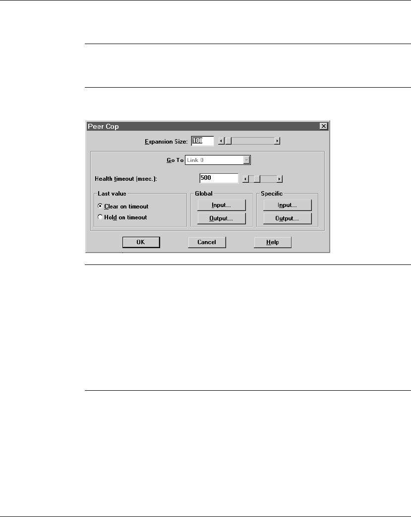
Other Default Settings in the Peer Cop Dialog Box
Overview This section describes the default settings for Health Timeout and Last Value.
Diagram The first time you access the Peer Cop dialog box, the following screen appears:
Health Timeout The default Timeout is 500 ms.
Timeout
is the maximum interval that Modbus Plus on a Peer-Copped device will
remain healthy without communication activity. If this interval is exceeded, the
device will clear its network health bit and will no longer try to communicate via
Modbus Plus.
The timeout interval must be in the range 20...2000 ms, and it must be specified as
an increment of 20 ms.
Continued on next page