MBX Driver Help MBX Driver for Modbus Plus Interface Adapters Version 8.
MBX Driver Help MBX DRIVER HELP MBX® Driver for Modbus Plus Interface Adapters Version 8.0 for Windows® 8/7/Vista/XP/Server 2012/Server 2008/Server 2003 Copyright © 1994-2014, Cyberlogic® Technologies Inc. All rights reserved. This document and its contents are protected by all applicable copyright, trademark and patent laws and international treaties.
MBX Driver Help TABLE OF CONTENTS Introduction ........................................................................................................5 Remote Connectivity ................................................................................................ 5 Running 16-Bit Software .......................................................................................... 5 Compatibility ...........................................................................................................
MBX Driver Help AT984 Tab ......................................................................................................... 75 MC984 Tab ........................................................................................................ 78 SA85 Tab ........................................................................................................... 79 SM85 Tab .......................................................................................................... 82 Peer Cop Tab ......
MBX Driver Help INTRODUCTION The MBX Driver provides device driver support under Windows for all Modbus Plus interface adapters from Schneider Electric. This includes support for popular cards such as SA85, PCI-85 and PCMCIA 416NHM21234, as well as the TSXCUSBMBP USB adapter. Since 1994, the MBX Driver has been the driver of choice for most automation engineers, and is used with virtually all Modbus Plus compatible software programs.
MBX Driver Help Blending MBX-Supported Networks The MBX driver family provides support for all Modicon networks through a common architecture, with identical programming interfaces. This means that an application that operates with one of the MBX family drivers, such as the MBX Driver, will work with the rest of them as well. Thus, virtually all Modbus Plus compatible software programs can operate over all Modicon-supported networks with no code modifications.
MBX Driver Help Cyberlogic Technologies Inc.
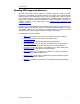
MBX Driver Help WHAT SHOULD I DO NEXT? The links below will take you directly to the section of this manual that contains the information you need to configure, use and troubleshoot the MBX Driver. Learn How the Driver Works If you are not familiar with the way that the MBX Driver handles communication, you should begin by reading Communication Using the MBX Driver.
MBX Driver Help COMMUNICATION USING THE MBX DRIVER Modbus Plus is a 1 Mbit/sec peer-to-peer communication network. Its architecture supports both solicited (Master Path) and unsolicited (Slave Path) communications. It also supports global data and Peer Cop communications. The message structure used by Modbus Plus is identical to the older Modbus message structure with the exception of the destination node address.
MBX Driver Help the controller. Such a routing might be: 15.37.0.0.0. This will route the message to the bridge at node address 15 of the local network, and from there it will go to the controller at node 37 on the remote network. As before, the zeros indicate that there is no further routing. By using all five routing array bytes, it is possible to route the message through up to four bridges before it reaches its final destination. A routing array of 5.42.17.3.
MBX Driver Help When the driver goes off-line, it will normally place the adapter card in the off-line state. However, if the system crashes, the driver will not have an opportunity to properly transition the adapter card’s state. In such a case, the adapter card would never respond to the command messages, resulting in lengthy timeouts on the Modbus Plus network.
MBX Driver Help controlling application, another application can immediately acquire this control. Starting and stopping applications or changing the Peer Cop resources by individual applications does not create any instability on the Modbus Plus network. Any Peer Cop related operation by one application does not affect concurrent Peer Cop operations from other applications. This is limited by the possibility of conflicts when attempting to control specific outputs at the same node address.
MBX Driver Help QUICK-START GUIDE Before the MBX Driver can be used, it must be properly configured. The configuration procedure involves creating one or more MBX devices and configuring them to work with the interface adapter card. Your software applications will then use these logical devices to communicate over the network. To accomplish this, you must run the MBX Driver Configuration Editor after you install the software.
MBX Driver Help PnP Adapter Quick-Start This section describes the procedure for adapters that support Plug and Play. To use this procedure, you must have one of the following adapter cards. PCI-85 (416NHM30030 or 416NHM30032) PCMCIA 416NHM21234 USB TSXCUSBMBP and XBTZGUMP If this is not the case, go to the Non-PnP Adapter Quick-Start section. The following steps show a typical configuration session. Use it only as a guideline of how to configure the most common features.
MBX Driver Help Note If you do not see the Found New Hardware message after inserting the PCMCIA 416NHM21234 card, check for the Schneider TSXMBP100 device (with a yellow exclamation point) under the Other Devices branch of the Device Manager. If the TSXMBP100 device is present, uninstall it (right-click and select uninstall) and then select the Scan for hardware changes from the Action menu. 3. When you are asked to connect to Windows Update, select No, not this time. 4. Click Next. 5.
MBX Driver Help PCI Card 1. Verify that the MBX Driver software is installed. Windows automatically detects and configures the PCI-85 when it is newly installed in the system. For this process to work correctly, the MBX Driver must be installed on your system before you install the card. 2. Turn off power and insert the adapter card into an empty PCI slot. 3. Turn the power back on.
MBX Driver Help 6. Select Install the software automatically (Recommended). 7. Click Next. 8. If the PC displays a warning that the software has not passed the Windows Logo Testing, select Continue Anyway. The system will automatically allocate resources for the PCI-85 card and create an MBX device with the next available device number. All parameters for the new device will default to standard settings, which may or may not fully match the desired settings.
MBX Driver Help Note If you do not see the Found New Hardware message after plugging in the adapter, check for a device with a yellow exclamation point under the Other Devices branch of the Device Manager. It may be shown as either TSXCUSBMBP Rev 2 or as Unknown Device. If such a device is present, uninstall it (right-click and select uninstall) and then select the Scan for hardware changes from the Action menu. 3. When you are asked to connect to Windows Update, select No, not this time. 4. Click Next.
MBX Driver Help 3. Locate the MBX Devices for Modicon Networks branch and expand it. 4. Select the device to be edited, right-click and select Properties from the context menu. The device properties window will open. Cyberlogic Technologies Inc.
MBX Driver Help 5. Choose the Device Settings tab. This tab allows configuration of all parameters related to the selected adapter card. 6. Select the proper Node Address for your adapter card. 7. The PCMCIA 416NHM21234 card can only operate in polled mode and we recommend that you use the default Polling Interval value of 20 msec. Proceed to Configuring Peer Cop Communications to continue. Configuring Peer Cop Communications 1.
MBX Driver Help 2. Click the Global Inputs button. The Global Input Configuration window will open. Note Up to 32 words of global input data may be requested from each Modbus Plus node configured here, with the limitation that the total amount of requested data must not exceed 500 words. Cyberlogic Technologies Inc.
MBX Driver Help 3. Select an MB+ Node intended to receive global data, and then click the Edit button. 4. From the drop-down box, select the number of words of global data to be requested from the node. 5. Repeat this procedure until all nodes that will receive global data are configured. 6. Click the OK button to return to the Device Settings tab. Cyberlogic Technologies Inc.
MBX Driver Help 7. Click the Specific Outputs button. The Specific Output Configuration window will open. Note Peer Cop communications can send up to 32 words of specific output data to each node on a Modbus Plus network. The total amount of specific output data sent from all applications through a single host interface adapter must not exceed 500 words. Cyberlogic Technologies Inc.
MBX Driver Help 8. Select an MB+ Node intended to receive specific output data, and then click the Edit Words button. 9. Select the proper number of words from the list and press the Enter key. 10. Click the Default Data button. Cyberlogic Technologies Inc.
MBX Driver Help Note The Default Data for a word is the value that the driver will use before any application overwrites it. All specific output data words default to zero, but you can specify a different value. 11. In the Display Mode section, select Hex, Decimal or Binary. 12. Select a word to edit and click the Edit button. Enter the new data value and press the Enter key. Repeat this step for every data word that you want to edit.
MBX Driver Help 13. Select an MB+ Node and click the Edit Exit Mode button. Note When the user application exits (either normal or abnormal termination), the specific outputs controlled by this application may be left in their last state or restored to their default state by the driver. Here you can choose how each node behaves. 14. Select Default Value or Last Value from the list and press the Enter key. Cyberlogic Technologies Inc.
MBX Driver Help 15. Repeat the specific output configuration procedure until all nodes have been configured. 16. Click the OK button to return to the Device Settings tab. 17. Click the Specific Inputs button. The Specific Input Configuration window will open. Note Up to 32 words of specific input data may be requested from each Modbus Plus node, with the limitation that the total amount of requested data must not exceed 500 words. Cyberlogic Technologies Inc.
MBX Driver Help 18. Select an MB+ Node that will provide specific input data, and then click the Edit button. 19. Select the number of desired words from the drop-down box. 20. Repeat the specific input configuration procedure until all nodes that will provide specific input data have been configured. 21. Click the OK button to return to the Device Settings tab. Cyberlogic Technologies Inc.
MBX Driver Help 22. From the Global Output Words drop-down, select the default number of global output data words to be transmitted by this adapter card. Note By default, the driver will not transmit any global output data until a user application writes to the global output data buffer. However, the driver can be configured to transmit up to 32 words of global output data even before any application writes to this buffer. The data buffer will be set to zero. 23.
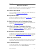
MBX Driver Help Proceed to Configuring the MBX Gateway Server to continue. Configuring the MBX Gateway Server The MBX Driver comes with the MBX Gateway Server. The MBX Gateway Server allows remote nodes to access all configured MBX devices present on the system that is running the MBX Gateway Server. Refer to the MBX Gateway Driver section for more information on this capability.
MBX Driver Help 4. You must enter a TCP port that is not used elsewhere in the system. The default, 53335, will work for most installations, but this port may be taken in some unusual cases. If that applies to your system, the system administrator will assign a different port value that you must enter in the Port Number field. 5. If your system uses a firewall, you must configure it to permit MBX Gateway communication. The procedure will depend upon the firewall you are using.
MBX Driver Help 3. The right pane of the screen provides shortcuts to troubleshooting and backup/restore tools. Run the MBX Demo program after configuring the MBX Driver to verify that the driver is configured and running properly. Detailed instructions for running this utility are included in the Validation & Troubleshooting section. When you are satisfied that the driver is correctly configured, proceed to Backing Up Your Configuration.
MBX Driver Help 3. Browse for the desired backup directory. By default, the last-used directory will be selected. 4. Enter the File name you want to use for your configuration backup file, and then click the Save button to complete the backup operation. Non-PnP Adapter Quick-Start This section describes the procedure for adapters that do not support Plug and Play. You must use this procedure for the following adapters.
MBX Driver Help After completing this procedure, you will have a fully-configured MBX device and will be able to confirm that the driver is running and communicating with other nodes on your network. To begin, go to Creating a Non-PnP Device. Creating a Non-PnP Device 1. From the Windows Start menu, go to the product suite you have installed. Next, open the Configuration submenu and select MBX Device Drivers. Running the editor for the first time displays the above screen.
MBX Driver Help 2. Click the New button and select SA85 from the drop-down list. The MBX Driver Configuration Editor will automatically dispatch the SA85 Configuration Editor. Proceed to Configuring Device Settings to continue. Configuring Device Settings The SA85 Configuration Editor has three configuration tabs. By default, the card configuration tab is selected. This tab allows configuration of all parameters related to the selected adapter card.
MBX Driver Help 1. Select the Memory Address that matches the DIP switch settings on your card. 2. Select the MBX Driver Control tab to configure the startup options. 3. Select the Automatic startup type. In this mode, the driver automatically starts during the system boot. This is the recommended mode of operation. Cyberlogic Technologies Inc.
MBX Driver Help Proceed to Configuring Peer Cop Communications to continue. Configuring Peer Cop Communications 1. Select the Peer Cop tab. 2. If you will not use Peer Cop communication, clear the Enable Peer Cop check box, click Close, and then proceed directly to Configuring the MBX Gateway Server. If you will use Peer Cop communication, check the Enable Peer Cop check box and continue with this section. 3. Click the Global Inputs button. The Global Input Configuration window will open.
MBX Driver Help 4. Select an MB+ Node intended to receive global data, and then click the Edit button. 5. From the drop-down box, select the number of words of global data to be requested from the node. 6. Repeat this procedure until all nodes that will receive global data are configured. 7. Click the OK button to return to the Peer Cop tab. Cyberlogic Technologies Inc.
MBX Driver Help 8. Click the Specific Outputs button. The Specific Output Configuration window will open. Note Peer Cop communications can send up to 32 words of specific output data to each node on a Modbus Plus network. The total amount of specific output data sent from all applications through a single host interface adapter must not exceed 500 words. Cyberlogic Technologies Inc.
MBX Driver Help 9. Select an MB+ Node intended to receive specific output data, and then click the Edit Words button. 10. Select the proper number of words from the list and press the Enter key. 11. Click the Default Data button. Cyberlogic Technologies Inc.
MBX Driver Help Note The Default Data for a word is the value that the driver will use before any application overwrites it. All specific output data words default to zero, but you can specify a different value. 12. In the Display Mode section, select Hex, Decimal or Binary. 13. Select a word to edit and click the Edit button. Enter the new data value and press the Enter key. Repeat this step for every data word that you want to edit.
MBX Driver Help Note When the user application exits (either normal or abnormal termination), the specific outputs controlled by this application may be left in their last state or restored to their default state by the driver. Here you can choose how each node behaves. 15. Select Default Value or Last Value from the list and press the Enter key. 16. Repeat the specific output configuration procedure until all nodes have been configured. 17. Click the OK button to return to the Peer Cop tab.
MBX Driver Help 18. Click the Specific Inputs button. The Specific Input Configuration window will open. Note Up to 32 words of specific input data may be requested from each Modbus Plus node, with the limitation that the total amount of requested data must not exceed 500 words. Cyberlogic Technologies Inc.
MBX Driver Help 19. Select an MB+ Node that will provide specific input data, and then click the Edit button. 20. Select the number of desired words from the drop-down box. 21. Repeat the specific input configuration procedure until all nodes that will provide specific input data have been configured. 22. Click the OK button to return to the Peer Cop tab. Cyberlogic Technologies Inc.
MBX Driver Help 23. From the Global Output Words drop-down, select the default number of global output data words to be transmitted by this adapter card. Note By default, the driver will not transmit any global output data until a user application writes to the global output data buffer. However, the driver can be configured to transmit up to 32 words of global output data even before any application writes to this buffer. The data buffer will be set to zero. 24.
MBX Driver Help 2. Select the desired mode of operation among the Startup Type choices. If you want to use the MBX Gateway Server and you want it to start whenever the system is booted, select Automatic. This is the recommended setting for systems that will use the Gateway Server. If you want to use the MBX Gateway Server and want to control it manually, choose Manual. If you do not want to use the MBX Gateway Server, choose Disabled.
MBX Driver Help 1. Select the Diagnostics tab. 2. The left pane of this screen shows all MBX product components installed on your system. This information, including the version numbers, may be requested if you call for technical support. This screen also tells you if the software has been activated or if it is running in the two-hour demo mode. Caution! If you are running in demo mode, the MBX products will stop after two hours of operation and will resume after the system is restarted. 3.
MBX Driver Help 1. Select the Diagnostics tab of the MBX Driver Configuration editor. 2. Click the Backup… button. 3. Browse for the desired backup directory. By default, the last-used directory is selected. 4. Enter the File name you want to use for your configuration backup file, and then click the Save button to complete the backup operation. Cyberlogic Technologies Inc.
MBX Driver Help CONFIGURATION EDITOR REFERENCE Before the MBX Driver can be used, it must be properly configured. The configuration procedure involves creating one or more MBX devices and configuring them to work with your network adapter cards. This section provides a detailed description of each of the configuration editor features. If you are a new user and want a procedure to guide you through a typical configuration session, refer to the Quick-Start Guide.
MBX Driver Help MBX Device This column contains a device number that the editor assigns to every MBX device installed in the system. This is not the Modbus node address. By default, the editor will try to use consecutive numbers for the devices starting from 0. However, this is not a requirement. Device Type This column identifies the type of the MBX device, such as PCI-85, Ethernet MBX or MBX Gateway. Device Description This is a user-assigned text for device description.
MBX Driver Help Delete Select an MBX device and click this button to delete it. More... Select an MBX device and click this button for additional editing features. You can change the device type or edit the Device Description field. Creating a New MBX Device Click the New button or right-click inside the list window and select New from the context menu. Then select a non-PnP interface adapter or other device type from the drop-down list.
MBX Driver Help Changing the Device Type This can be done only to change a non-PnP device type to another non-PnP device type. Select the device and click the More… button or right-click and select Change Type from the context menu. From the drop-down list select the new device type for your MBX device. Upon selecting the new device type, the MBX Driver Configuration Editor will automatically dispatch the appropriate device configuration editor.
MBX Driver Help Disabled When this option is selected, the MBX Gateway Server will not run. Start In Automatic or Manual mode, click this button to start the MBX Gateway Server. Stop In Automatic or Manual mode, click this button to stop the MBX Gateway Server. Status This tells you whether the MBX Gateway Server is running, stopped, starting or stopping. TCP Port The port used here must not be used elsewhere in the system.
MBX Driver Help You must enter a TCP port that is not used elsewhere in the system. The default, 53335, will work for most installations, but this port may be taken in some unusual cases. If that applies to your system, the system administrator will assign a different port. Configuring the Firewall If your system uses a firewall, you must configure it to permit MBX Gateway communication. The procedure shown here is for the Windows XP firewall.
MBX Driver Help Diagnostics Tab The diagnostic features will help you to confirm that the driver is running and is properly configured. They will also provide important help if troubleshooting or technical support is needed. Installed MBX Driver Products This area shows all MBX product components installed on your system, along with their version numbers. This information may be requested if you call for technical support.
MBX Driver Help Note Some OEM versions of MBX products are pre-activated and do not require you to take any additional activation steps. License Type This field shows the licensing mode that the software is operating under. If the type displayed is 2 Hour Demo, the software will run for only two hours at a time, after which you must restart the system to obtain another two hours of use. To enable continuous, uninterrupted operation, you must activate the software.
MBX Driver Help Backup Configuration Use this procedure to backup your configuration. 1. Click the Backup… button. 2. Browse for the backup directory. By default, the last-used directory will be selected. 3. Enter the File name you want to use for your configuration backup file, and then click the Save button to complete the backup operation. Restore Configuration To restore a configuration that was previously backed up, use this procedure. 1. Click the Restore… button. Cyberlogic Technologies Inc.
MBX Driver Help 2. Browse for your configuration backup file. By default, the last used directory will be selected. 3. Select the backup file and click the Open button to complete the restore operation. Caution! After you finish restoring the configuration, restart the system to ensure proper operation of the restored devices. Configuration Backup/Restore Utility The MBX driver products include a utility program, ClMbxCfg.exe, that you can use to backup and restore MBX device configurations.
MBX Driver Help You can use different file names to maintain different versions of your backups. However, for most users, a single backup is sufficient. PnP Adapter Editor When you edit a PnP adapter configuration, the Device Manager dispatches the PnP Adapter Configuration editor. The editor consists of five tabs. Some tabs are standard for all device types and are automatically provided by the Device Manager.
MBX Driver Help PCI-85 (416NHM30030 or 416NHM30032) Device Settings Tab Node Address This is the Modbus Plus node address for the adapter. Valid node addresses range from 1 to 64. The default for this parameter is 1. Polling Interval This parameter specifies the polling interval, in milliseconds, that the driver will use when running in polled mode. The valid range for the Polling Interval is 20-1000 msec. The default value is 20 msec. Device Name This parameter assigns a name to identify the device.
MBX Driver Help Device Description This is a user-assigned text for device description. During device creation, a default description text will be assigned. The Device Description text has no effect on the MBX device operation. However, some applications using this device may be able to show this text. Peer Cop The PCI-85 card supports Peer Cop functionality. Refer to the Peer Cop section if you need to configure Peer Cop support.
MBX Driver Help Memory Range This parameter specifies the base address of the adapter card’s memory window. Two memory ranges are automatically selected by the system and should not be changed. Interrupt Request In interrupt mode, this parameter specifies the IRQ number for the interrupt line used. The interrupt line is automatically selected by the system and should not be changed by the user. The MBX Driver can operate in either polled mode or interrupt mode.
MBX Driver Help Node Address This is the Modbus Plus node address for the adapter. Valid Node Addresses range from 1 to 64. The default for this parameter is 1. Polling Interval This parameter specifies the polling interval, in milliseconds, that the driver will use when running in polled mode. The valid range for the Polling Interval is 20-1000 msec. The default value is 20 msec. Device Name This parameter assigns a name to identify the device.
MBX Driver Help Memory Range This parameter specifies the base address of the adapter card’s memory window. Two memory ranges are automatically selected by the system and should not be changed. Removing the Card Note The PCMCIA 416NHM21234 card supports Plug and Play and can be plugged in at any time, before or after the system boot. However, before removal, you must exit all applications that are using the card and stop the driver. To stop the driver, follow the procedure below. 1.
MBX Driver Help USB TSXCUSBMBP and XBTZGUMP There are two versions of the TSXCUSBMBP, Rev. 1 and Rev. 2. Both types have a Device Settings tab, and Rev. 2 adapters also have a Firmware tab. Unlike the other PnP adapters, the TSXCUSBMBP adapter does not have a Resources tab. The XBTZGUMP adapter is not licensed for full operation under Windows, so the driver will operate only for two hours at a time. For continuous operation, use a TSXCUSBMBP adapter.
MBX Driver Help Node Address This is the Modbus Plus node address for the adapter. Valid node addresses range from 1 to 64. The default for this parameter is 1. Device Name This parameter assigns a name to identify the device. The default for this parameter is Clmbx#, where # is the selected device number. Device Description This is a user-assigned text for device description. During device creation, a default description text will be assigned.
MBX Driver Help Version reported by the adapter This is the firmware version that is currently in the TSXCUSBMBP adapter. Version available for programming This is the firmware version that is on your hard drive and that can be programmed into the adapter. Reprogram Click this button to program the firmware from the hard drive into the TSXCUSBMBP adapter. Normally, you would do this only if the version on the adapter is outdated or corrupted.
MBX Driver Help Enable Peer Cop This check box enables Peer Cop communication for the adapter card. By default, Peer Cop communication is disabled. Enable it only if your applications require this type of communication. Unnecessary transmissions of Peer Cop related data may slow down the token rotation and consequently may affect the communication throughput for other types of messages. Global Inputs Click this button to edit the global input data.
MBX Driver Help Global Output Words By default, the driver will not transmit global output data until a user application writes to the global output data buffer. However, the driver can be configured to transmit up to 32 words of global output data even before any application writes to this buffer. Refer to Peer Cop Communications in the Communicating Using the MBX Driver section for more information.
MBX Driver Help Setting Words Per Node To Read Select an MB+ Node intended to receive global data. Click the Edit button or right-click and select Edit from the menu. Select the number of words of global data to read from the list and press Enter. Specific Outputs Configuration Note Peer Cop communications can send up to 32 words of specific output data to each node on a Modbus Plus network.
MBX Driver Help Setting Default Data To Write Select an MB+ Node to configure. Click the Default Data button or right-click in the Words Per Node column and select Default Data from the context menu. You will see the following screen. By default, all specific output data words are filled with zeros. The default data can be viewed and edited in Hex, Decimal or Binary. Select Hex, Decimal or Binary Display Mode. Select a word to edit and click the Edit button. Enter a new data value and press Enter.
MBX Driver Help Specific Inputs Configuration Note Up to 32 words of specific input data may be requested from each Modbus Plus node, with the limitation that the total amount of requested data must not exceed 500 words. Setting Words Per Node to Read Select an MB+ Node that will provide specific input data. Click the Edit button or rightclick and select Edit from the context menu. Select the number of Words Per Node to read from the list and press Enter.
MBX Driver Help Registration Information This area shows the MBX product installed on your system, along with its version and serial numbers. This information may be requested if you call for technical support. This area also tells you if the software has been activated or if it is running in demo mode. Product Package MBX products are sold and installed as packaged suites, such as the MBX Driver Suite and MBX OPC Server Suite. This field indicates the suite that is installed on your system.
MBX Driver Help Note Some OEM versions of MBX products are pre-activated and do not require you to take any additional activation steps. License Type This field shows the licensing mode that the software is operating under. If the type displayed is 2 Hour Demo, the software will run for only two hours at a time, after which you must restart the system to obtain another two hours of use. To enable continuous, uninterrupted operation, you must activate the software.
MBX Driver Help AT984 Tab MC984 Tab SA85 Tab SM85 Tab At the end are sections covering the Peer Cop Tab and MBX Driver Control Tab, which are common to all adapter card types. AT984 Tab Network Device Name This parameter allows the user to assign a name to identify the device. The default for this parameter is ClMbx#, where # is the selected device number.
MBX Driver Help respond to the command messages, resulting in lengthy timeouts on the Modbus Plus network. Therefore, we strongly recommend that you enable the watchdog timer for adapter cards that support it. Timeout The user may select the desired timeout interval, or disable the watchdog timer. The recommended timeout is 2.5 seconds for adapter cards that support the watchdog timer. For compatibility with older adapter cards, the default value is Disabled.
MBX Driver Help 1. Shutdown Windows and turn off your computer. 2. If the adapter card is already installed in the computer, open the case and remove the card. It will look similar to the diagram above. 3. Locate the IRQ jumper block on the card. Move the IRQ jumper to the desired IRQ position. 4. Insert the adapter card back into the computer and turn on the computer. Refer to the Validation & Troubleshooting section to verify the card’s operation.
MBX Driver Help MC984 Tab Network Device Name This parameter allows the user to assign a name to identify the device. The default for this parameter is ClMbx#, where # is the selected device number. Adapter Watchdog Timer Adapter cards that support Peer Cop have a diagnostic watchdog timer that, when enabled, automatically places the adapter card in the off-line state if the host is inactive for a pre-configured period.
MBX Driver Help Operation Polling Interval This parameter specifies the polling interval, in milliseconds, that the driver will use when running in polled mode. The valid range for the polling interval is 20-1000 msec. The default value is 20 msec. MicroChannel Slot Number This allows you to specify the slot number for the adapter card, a requirement for all Micro Channel cards. Valid Slot Numbers start from 1. The default for this parameter is 1.
MBX Driver Help Network Device Name This parameter allows the user to assign a name to identify the device. The default for this parameter is ClMbx#, where # is the selected device number. Adapter Watchdog Timer Adapter cards that support Peer Cop have a diagnostic watchdog timer that, when enabled, automatically places the adapter card in the off-line state if the host is inactive for a pre-configured period.
MBX Driver Help Resources Memory Address This parameter specifies the base address of the adapter card. This address must match the switch settings on the card and must be unique for each adapter card. The default for this parameter is D0000. Interrupt IRQ When interrupt mode is selected, this parameter specifies the IRQ number for the interrupt line used. This IRQ number must match the IRQ setting on the adapter card and must be a unique value for each card in the system.
MBX Driver Help 7. Locate the IRQ jumper block on the card. Move the IRQ jumper to the desired IRQ position. 8. Insert the adapter card back into the computer and turn on the computer. Refer to the Validation & Troubleshooting section to verify the card’s operation. For more information on adapter card configuration, refer to Modicon IBM Host Based Devices User's Guide from Schneider Electric (Order #890 USE 102 00).
MBX Driver Help Adapter Watchdog Timer Adapter cards that support Peer Cop have a diagnostic watchdog timer that, when enabled, automatically places the adapter card in the off-line state if the host is inactive for a pre-configured period. While the driver is operational, it will always place an adapter card in the off-line state when transitioning from the on-line to the off-line mode.
MBX Driver Help Peer Cop Tab This tab allows you to configure the Peer Cop communication settings. These settings are relevant only for the adapter cards supporting Peer Cop. Otherwise all settings will be ignored. Enable Peer Cop This check box enables Peer Cop communication for the adapter card. By default, Peer Cop communication is disabled. Enable it only if your applications require this type of communication.
MBX Driver Help Global Output Words By default, the driver will not transmit global output data until a user application writes to the global output data buffer. However, the driver can be configured to transmit up to 32 words of global output data even before any application writes to this buffer. Refer to Peer Cop Communications in the Communication Using the MBX Driver section for more information.
MBX Driver Help Setting Words Per Node To Read Select an MB+ Node intended to receive global data. Click the Edit button or right-click and select Edit from the menu. Select the number of words of global data to read from the list and press Enter. Specific Outputs Configuration Note Peer Cop communications can send up to 32 words of specific output data to each node on a Modbus Plus network.
MBX Driver Help Setting Default Data To Write Select an MB+ Node to configure. Click the Default Data button or right-click in the Words Per Node column and select Default Data from the context menu. You will see the following screen. By default, all specific output data words are filled with zeros. The default data can be viewed and edited in Hex, Decimal or Binary. Select Hex, Decimal or Binary Display Mode. Select a word to edit and click the Edit button. Enter a new data value and press Enter.
MBX Driver Help Specific Inputs Configuration Note Up to 32 words of specific input data may be requested from each Modbus Plus node, with the limitation that the total amount of requested data must not exceed 500 words. Setting Words Per Node to Read Select an MB+ Node that will provide specific input data. Click the Edit button or rightclick and select Edit from the context menu. Select the number of Words Per Node to read from the list and press Enter.
MBX Driver Help Automatic When this option is selected, the MBX Driver will start when Windows boots. Manual When this option is selected, the MBX Driver will not start when Windows boots, but you can control it manually using the Start and Stop buttons. Disabled When this option is selected, the MBX Driver will not run. Start In Automatic or Manual mode, click this button to start the MBX Driver. Stop In Automatic or Manual mode, click this button to stop the MBX Driver.
MBX Driver Help Selecting the Startup Type Select the desired mode among the Startup Type choices. If you want the MBX Driver to start whenever the system is booted, select Automatic. This is the recommended setting for systems that will use the MBX Driver. If you want to use the MBX Driver and want to control it manually, choose Manual. The driver will not start on boot-up; instead you must use the Start and Stop buttons to control it. If you do not want to use the MBX Driver, choose Disabled.
MBX Driver Help VALIDATION & TROUBLESHOOTING The following sections describe how the MBX Demo and Performance Monitor are used to verify that the MBX devices are configured correctly. If you are not sure if your adapter card supports Peer Cop, the Determining Peer Cop Support section will tell you how to find out. If you are having difficulties communicating through an MBX device, the troubleshooting sections can help you determine the nature of the problem.
MBX Driver Help The simple command-line interface mimics earlier tools familiar to most users. It displays menu choices that take the user to secondary level screens. Press Esc at any screen to return to the main menu shown above. Press Esc in the main window to exit the program. [1] Set Device Number When the MBX Demo program starts, the device number defaults to 0. To change it, press 1.
MBX Driver Help [B] Read Device Status From the main menu, press B. This launches the device status screen, which shows all active nodes on the network. In the Active Node List grid, the letter I designates the node you are working from and the letter U designates other nodes found on the network. Verify that all expected nodes are shown and that the node addresses are correct, then press Esc to return to the main menu.
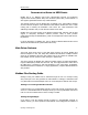
MBX Driver Help After viewing the information, press Esc to return to the main menu. [2] Read Selected Node To read data from registers on a specific node, press 2. Enter the routing path of the node you want to read from. You may enter the full Modbus routing path of the node, but it is not necessary to enter trailing bytes that are 0. In the example shown, the full routing path was 7.0.0.0.0, so entering just 7 was sufficient. A routing path of 9.24.19.0.0 could be entered as 9.24.19.
MBX Driver Help driver family, allow users to monitor relevant performance information. Multiple devices can be monitored simultaneously for comparison. To run the program, open the Windows Start menu and locate the product suite you have installed. From there, go to Diagnostics and select Performance Monitor. Alternatively, go to the Diagnostics tab of the MBX Driver Configuration Editor and click the Performance Monitor button.
MBX Driver Help 1. When the Performance Monitor program starts, click the + button on the tool bar. Cyberlogic Technologies Inc.
MBX Driver Help 2. Select Cyberlogic MBX Devices from the Performance object list. Cyberlogic Technologies Inc.
MBX Driver Help 3. Choose a counter and the MBX device, and then click Add. Repeat this for all the counters you want to view. 4. Click Close. The counters you chose will then be displayed in graphical format. Cyberlogic Technologies Inc.
MBX Driver Help Determining Peer Cop Support Before determining whether your card supports Peer Cop, be sure the card is installed and properly configured. Refer to the Quick-Start Guide section for more information. Note You may use the following procedure to determine if Peer Cop is supported even if Peer Cop was not enabled during the board configuration. Once you verify that your card functions correctly, follow the procedure described below. 1. Start the MBX Demo program. 2.
MBX Driver Help Alternatively, click the Event Viewer button on the Diagnostics tab of the MBX Driver Configuration Editor. 2. If you are looking for events relating to the MBX Driver, select the System branch from the Event Viewer tree, and look for entries in the Source column named CLMBX or ClMbxPnP. For other types of events, select the Application branch from the Event Viewer tree, and look for entries in the Source column that begin with Cyberlogic.
MBX Driver Help 4. For further descriptions of the error log messages, refer to the MBX Driver Messages section. Cyberlogic Technologies Inc.
MBX Driver Help MBX Driver Messages The USB adapter for failed the dual-port memory diagnostics. Try another adapter card. This indicates a hardware failure. The USB adapter for failed interface diagnostics. Try another adapter card. This indicates a hardware failure. The USB adapter for failed peer cop initialization. Check peer cop configuration and restart the driver. Try another adapter card. This indicates a hardware failure.
MBX Driver Help Total number of data words in parameter for device exceeds 500 word limit. (End of dump data has total length value). Check device configuration and restart the driver. This indicates an error in the configuration of the specified MBX device. Correct the configuration and restart the driver. Failed to open binary file for . Reinstall the product and restart the driver.
MBX Driver Help This is a -hour promotional copy of the MBX Driver. The application started at and the driver will stop at . This is a time-limited installation of the software. After the stop time, the driver will not allow any further I/O operations. This is a promotional copy of the MBX Driver. The allowed operation time has expired. The I/O operations of the MBX Driver have been disabled. This is a time-limited installation of the software.
MBX Driver Help Adapter card ID for in selected slot does not match the expected card ID. Invalid configuration parameter. MCA adapter cards, such as SM85 and MC984, have unique ID codes used to identify them. The card inserted in the specified MCA slot does not match the expected card ID. Adapter card initialization for failed. The AIDA command timed-out. Please contact technical support of manufacturer for more assistance.
MBX Driver Help devices in the system. Invalid configuration parameter. One of the requested system resources (such as the memory address or interrupt IRQ), has already been allocated to a different device. Mapping selected interrupt into system interrupt vector for failed. Check device configuration and restart the driver. Unreported interrupt already used by another device driver. Mapping selected physical memory address to logical address space for failed.
MBX Driver Help The interface to the adapter card for has crashed (Crash code: 0x). Check for possible conflicts with other devices in the system. Try another adapter card. May indicate a faulty card. The slot number in the selected bus for device is not supported by this computer system. Invalid configuration parameter. Unexpected error in for . Please contact technical support of manufacturer.
MBX Driver Help Crash Codes Occasionally, due to adapter card malfunctions, the MBX Driver may detect an adapter card fault. In most cases, this is due to electrical interference, either internal or external to the computer system. However, it can also be an indication of a card failure. The MBX Driver tries to recover from these failures automatically. Every time a fault condition is detected, an internal adapter fault counter is incremented and the last crash code is recorded internally.
MBX Driver Help 0x8E XMTOKSVAR Fatal Transmit-OK MAC-state 0x8F NORCVBUF Fatal No receive buffer free 0x90 BADINXLEN Fatal Bad input-transfer length 0x91 RESBUFERR Fatal Reserved rcv-buf error 0x92 BADTCSVAR Fatal Bad trans-control state 0x93 BADWRKREQ Fatal Bad work request bit 0x94 OVFDATQUE Fatal Node-queue overflow 0x95 BADDATQUE Fatal Bad data-queue overflow 0x96 NOPATHERR Fatal Empty data-path error 0x97 BADPTHINX Fatal Bad path search index 0x98 BADDSPATH Fa
MBX Driver Help In polled mode, the recommended polling rate to use for optimum performance is 20 msec. Verify that the adapter card’s memory address is unique and does not conflict with other cards in the system. Check for error messages in the Event Viewer. They may aid in detecting hardware conflicts. I’ve installed the software. What’s next? The next step is to configure a device. You will need to know the card’s memory address and interrupt. Refer to the Quick-Start Guide section for more details.
MBX Driver Help few days or even weeks, but then drops communication. If I reboot, it restarts, and then the failure pattern repeats. What’s going on? The TSXCUSBMBP is powered by the computer’s USB port. These ports vary widely in the amount of current they can supply, and some do not supply enough current to meet the adapter’s needs. In that case, the adapter may work for a while and then fail at random intervals. This is more common with notebooks, but it can happen on desktop and tower systems as well.
MBX Driver Help APPENDIX: MBX ARCHITECTURE AND COMPANION PRODUCTS The MBX Driver is part of the Cyberlogic MBX family. This family consists of several wellintegrated products that provide connectivity for Modbus, Modbus Plus and Modbus TCP (Ethernet) networks in distributed environments. This section illustrates the layout of the MBX architecture. It includes a description of each MBX component along with suggested methods for employing them to support Modicon networks.
MBX Driver Help the MBX Driver takes advantage of the event-driven, multitasking, multithreaded features of Windows operating systems. The driver includes the MBX Gateway Server for remote access by the MBX Gateway Driver and is fully compatible with all other components of the MBX family.
MBX Driver Help The Serial MBX Driver is included in the following products: MBX OPC Enterprise Suite MBX OPC Premier Suite MBX OPC Server Suite MBX Bridge Suite MBX Driver Suite (Some OEM versions do not include the Serial MBX Driver.) MBX Gateway Driver The MBX Gateway Driver lets applications use MBX devices on remote MBX Gateway Server nodes as though they were on the local system.
MBX Driver Help The Virtual MBX Driver is fully compatible with all MBX components and requires at least one of these drivers to operate: MBX Driver Ethernet MBX Driver Serial MBX Driver MBX Gateway Driver The Virtual MBX Driver is included in the following products: MBX OPC Enterprise Suite MBX OPC Premier Suite MBX OPC Server Suite MBX Bridge Suite MBX Driver Suite MBX Bridge The MBX Bridge seamlessly routes messages between MBX-compatible devices.
MBX Driver Help The MBX OPC Server is included in the following products: MBX OPC Enterprise Suite MBX OPC Premier Suite MBX OPC Server Suite MBX SDK Software developers can use the MBX Software Development Kit to provide connectivity to Modbus, Modbus Plus and Modbus TCP networks from their 32-bit C/C++ applications. The SDK supports two styles of interfaces, NETLIB and Cyberlogic's high-performance MBXAPI.