
Specifications


Bulletin No. VVDED397044US R12/00 Section 2—Modbus Plus Overview
December 2000 Global Data Transmission
© 1998–2000 Schneider Electric All Rights Reserved
47
To optimize network response time, keep the number of global data
registers to a minimum.
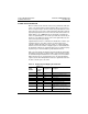
EXAMPLE OF SETTING UP PEER COP AND GLOBAL DATA SERVICE
This section describes the steps for configuring the drive controller so that
a PLC at address 3 can control the drive controller via five peer cop
registers and display these states via 14 global data transfers. It is
assumed that the PLC is configured to send five peer cop data items to
the drive controller and receive 14 global data transfers.
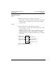
1. With the drive controller powered down, set its MODBUS PLUS
address using switches 1 to 6. Leave switches 7 and 8 at zero. For
example, to select address 4, set switches 1 and 2 to 1. The address
can be displayed using operator keypad menu 8, AdrC.
2. Connect the drive controller to the line supply.
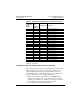
11 483 DF1 Register of active faults No. 1
12 484 DF2 Register of active faults No. 2
13 462 DP1 Number of past fault No. 1
14 463 EP1 Status of past fault No. 1
15 464 DP2 Number of past fault No. 2
16 465 EP2 Status of past fault No. 2
17 466 DP3 Number of past fault No. 3
18 467 EP3 Status of past fault No. 3
19 468 DP4 Number of past fault No. 4
20 469 EP4 Status of past fault No. 4
21 470 DP5 Number of past fault No. 5
22 471 EP5 Status of past fault No. 5
23 472 DP6 Number of past fault No. 6
24 473 EP6 Status of past fault No. 6
25 474 DP7 Number of past fault No. 7
26 475 EP7 Status of past fault No. 7
27 476 DP8 Number of past fault No. 8
28 477 EP8 Status of past fault No. 8
29 478 IOLR Image of logic I/O
30 479 AI1R Image of analog input AI1
31 480 AI2R Image of analog input AI2
32 481 AI3R Image of analog input AI3
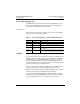
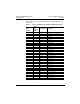
Table 14: Display Register Mapping w/ Global Data (Continued)
Global Data
Order
Number
Address of
Drive
Controller
Variable
Designation Description