
Specifications


Bulletin No. VVDED397044US R12/00 Section 2—Modbus Plus Overview
December 2000 Peer Cop
© 1998–2000 Schneider Electric All Rights Reserved
45
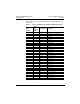
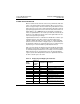
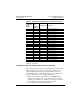
Table 13 lists the control and adjustment variables mapped through peer
cop transfers.
Table 13: Control and Adjustment Variables Mapped w/Peer Cop
Peer Cop
Order
Number
Address of
Drive
Controller
Variable
Designation Description
1 400 CMD DRIVECOM command register
2 401 LFR Frequency reference in line mode
3 402 CMI Internal command register
4 250 HSP High speed
5 251 LSP Low speed
6 252 ACC Acceleration
7 253 DEC Deceleration
8 254 UFR IR compensation
9 255 FLG Frequency loop gain
10 256 PFL U/F control ratio profile
11 257 STA Damping
12 258 ITH Thermal protection current
13 259 SLP Slip compensation
14 260 AC2 Acceleration 2
15 261 DE2 Deceleration 2
16 262 JOG JOG frequency
17 263 JGT Anti-repeat delay (JOG)
18 264 SP2 Preset speed 2
19 265 SP3 Preset speed 3
20 266 SP4 Preset speed 4
21 267 SP5 Preset speed 5
22 268 SP6 Preset speed 6
23 269 SP7 Preset speed 7
24 270 IDC Injection current
25 271 TDC Injection time
26 272 TLS Maximum time at low speed (LSP)
27 273 BRL Brake release threshold
28 274 BEN Brake engage threshold
29 275 BRT Brake release time
30 276 BET Brake engage time
31 277 IBR Brake release current threshold
32 278 TL2 Second torque limit