
Specifications


Section 2—Modbus Plus Overview Bulletin No. VVDED397044US R12/00
Peer Cop December 2000
44
© 1998–2000 Schneider Electric All Rights Reserved
1. Select Peer Cop and press ENT. The peer cop status appears. Select
YES using the ▲▼ keys and press ENT.
2. Select Control Node and press ENT. Using the ▲▼ keys, enter the
number of the node from which the peer cop data is to be received.
3. Select Number Registers and press ENT. Using the ▲▼ keys, enter
the number of variables to be received.
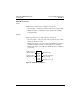
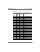
Received peer cop data is mapped in the three control words CMD, LFR,
and CMI (addresses 400 to 402) and in the first 29 adjustment variables
from HSP to TL2 (addresses 250 to 278). If a write message is received
for peer copped registers, it is refused and a negative acknowledgment is
returned.
If no peer cop data is received from the control node within the specified
time-out period, the drive controller switches to CNF fault mode and
authorizes other nodes to write to the peer copped registers via message
handling.
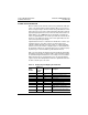
You can specify the number of peer cop registers required.
• If you enter 2 in the Num Registers field of the 8—Communication
menu and in the length field of the peer cop screen in MODSOFT
software, variables W400 (CMD) and W401 (LFR) receive peer cop
data.
• If you enter 4 in the Num Registers field, then control variables W400
to W402 receive the first three words of peer cop data (1 to 3), and
adjustment variable W250 receives peer cop data word 4.
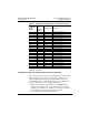
Adjust the number of peer cop registers configured with the peer cop
screen in MODSOFT software according to the application requirements.