
Specifications


Section 2—Modbus Plus Overview Bulletin No. VVDED397044US R12/00
MSTR Block December 2000
42
© 1998–2000 Schneider Electric All Rights Reserved
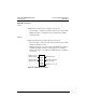
Top Node Content
The 4x register entered in the top node is the first of nine contiguous
holding registers that comprise the control block (see Table 11).
NOTE: You must understand MODBUS PLUS routing path procedures
before programming an MSTR instruction. For a complete overview, refer
to the
MODBUS PLUS Network Planning and Installation Guide,
890 USE 100 00
.
Middle Node Content
The 4x register entered in the middle node is the first in a group of
contiguous holding registers that comprise the data area.
• For operations that provide the communication processor with data—
such as a write operation—the data area is the source of the data.
• For operations that acquire data from the communication processor—
such as a read operation—the data area is the destination for the data.
Bottom Node Content
The integer value entered in the bottom node specifies the length—the
maximum number of registers—in the data area. Although the typical
MODBUS PLUS length may range from 1 to 100 registers, the ATV58
drive controller range is 1 to 60 registers.
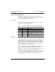
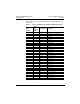
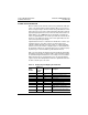
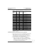
Table 11: Control Block Holding Registers
Register Content
Displayed Identifies one of the nine MSTR operations
1st implied Displays error status
2nd implied Displays length
3rd implied Displays MSTR operation-dependent information
4th implied
Routing 1 register, used to designate the address of the destination
node for a network message transaction.
5th implied Routing 2 register
6th implied Routing 3 register
7th implied Routing 4 register
8th implied Routing 5 register