
Specifications


Bulletin No. VVDED397044US R12/00 Section 2—Modbus Plus Overview
December 2000 MSTR Block
© 1998–2000 Schneider Electric All Rights Reserved
41
MSTR Block Structure
Inputs
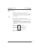
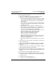
MSTR has two control points (see Figure 27 on page 41):
• Top node input — enables the instruction when top node input is ON.
• Middle node input — terminates the active operation when middle
node input is ON.
Outputs
MSTR can produce three possible outputs (see Figure 27):
• Top node output — echoes the state of the top node input (goes ON
while the instruction is active).
• Middle node output — echoes the state of the middle node input and
goes ON if the MSTR operation is terminated prior to completion.
• Bottom node output — goes ON when MSTR operation is completed
successfully.
Figure 27: MSTR Block Structure
Control
Block
Data
Area
MSTR
Length
Operation active
Operation terminated
unsuccessfully
Enables selected
MSTR operation
Terminates active
MSTR operation
Operation successful