
Specifications


Section 2—Modbus Plus Overview Bulletin No. VVDED397044US R12/00
MSTR Block December 2000
40
© 1998–2000 Schneider Electric All Rights Reserved
As a node on a MODBUS PLUS network, the ATV58 drive controller
cannot initiate messages, but all of its command (read and write),
adjustment (read and write), and display (read only) registers can be read
by other networked devices through messaging at any time, even when
the drive controller is running.
Other networked devices can write to:
• Command registers, as long as they are not peer cop registers and the
command semaphore is not taken
• Adjustment registers, as long as they are not peer copped
Other nodes cannot write to peer copped registers via message handling
except in the event of a peer cop time-out. If a write message is received
for peer copped registers, the message is refused and a negative
acknowledgment is returned.
MSTR BLOCK
Overview of MSTR Block
PLCs that support MODBUS PLUS communications have a special
MSTR (master) instruction with which nodes of the network can initiate
message transactions. The MSTR function allows you to initiate one of
nine possible network communications operations. Each operation is
designated by a code (see Table 10):
This section discusses read and write MSTR instruction blocks. For
additional information on Modbus instructions, refer to the
Ladder Logic
Block Library User Guide,
840 USE 10 100.
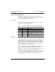
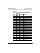
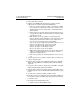
Table 10: MSTR Operation Codes
MSTR Operation Code MSTR Operation Code
Write Data 1 Get Remote Statistics 7
Read Data 2 Clear Remote Statistics 8
Get Local Statistics 3 Peer Cop Status 9
Write Global Database 5
Read Global Database 6