
Specifications


Section 1—Installation & Configuration Bulletin No. VVDED397044US R12/00
Parameter Setup December 2000
34
© 1998–2000 Schneider Electric All Rights Reserved
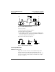
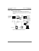
Example of MODBUS PLUS Network Operation
Figure 24 illustrates a typical MODBUS PLUS network with two
ALTIVAR 58 drive controllers as nodes. The figure illustrates that a single
node controls the drive controller by implicit reservation of the command
semaphore.
Figure 24: MODBUS PLUS Network Operation
Specific transfer with
peer cop enabled in
the ALTIVAR 58 drive
controller creates a
command node
(Node 1).
Modicon PLC
Node 1
HMI
Node 2
Node 4
Node 5
Global Data
HMI sends
messages
to read
data from
drive
controller 1
Specific transfer from
node 3 to node 5 is
ignored by drive
controller 2 since it has
peer cop reception
disabled. Specific
transfer from node 3 to
node 4 is ignored by drive
controller 2 since its
designated control node
is node 1. Node 3 can
send messages using
MSTR blocks to node 5.
Modicon
PLC Node 3
Node 6 on
MODBUS PLUS
Network 1
Bridge
Node 3
MODBUS PLUS
Network 2
Node 1
MODBUS PLUS
Network 1
Node 2Node 5Node 4
Peer cop node = Yes
Command node = 1
Drive 1 Drive 2
Peer cop
node = No