
Specifications


Bulletin No. VVDED397044US R12/00 Section 1—Installation & Configuration
December 2000 Parameter Setup
© 1998–2000 Schneider Electric All Rights Reserved
33
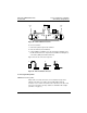
• At each connector, check the continuity between pin 1 and the
MODBUS PLUS cable shield ground point on the heat sink. Direct
continuity should not be present.
• Check for proper termination and insulation of individual drop twisted
pair shields.
If any check point fails, inspect the cable and all connections for damage
or miswiring, and correct the condition.
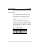
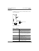
Figure 23: 9-Pin D-Shell Drop Cable Connector
PARAMETER SETUP
Configuring the Communication Parameters
Initial Power-Up
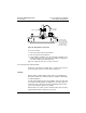
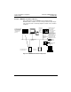
When the MODBUS PLUS card is initially powered up, it is automatically
recognized by the drive controller. It provides access to the
8—Communication menu on the operator keypad.
Configuration
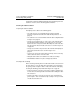
Select the 8—Communication menu (see Table 8 on page 36) to access
the option card configuration parameters. Using the keypad, enter “8 SL”
(Serial Link, Communication). The first parameter is the address of the
drive controller on the network. Because this parameter is physically
configured on the card with switches 1 to 6 (see “Setting the Drive
Controller Address” on page 12), it can only be read from the keypad.
NOTE: The communication parameters can only be modified with the
motor stopped.
Pin 1 Pin 5
Pin 9Pin 6
Pin 1 is the shield pin
Pins 2 and 3 are the signal pins