
Specifications


Section 1—Installation & Configuration Bulletin No. VVDED397044US R12/00
Trunk and Drop Cabling with Taps December 2000
32
© 1998–2000 Schneider Electric All Rights Reserved
Complete the network installation labeling by properly labeling each site’s
cabinet or enclosure, device mounting panel, and device.
Checking the Cable Installation
Inspecting the Cable Installation
Visually inspect the cable for the following points:
• The cable runs are consistent with the physical and electrical
protection requirement described in “Cable Routing Practices” on
page 19.
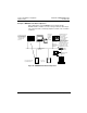
• The cable runs are consistent with the network cable routing illustrated
in Figure 16 on page 25.
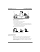
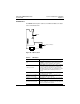
• The tap at each end drop site on each section of the network has its
two internal termination jumpers connected. They are connected
between the two center posts and the W and B posts at the side of the
tap opposite from the trunk cable connection, as shown in Figure 19
on page 28.
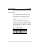
• The tap at each in-line drop site has its two internal terminal jumpers
disconnected and removed, as shown in Figure 18 on
page 27.
• Service loops exist on the trunk cable at each tap, and on each drop
cable at the node device end of the cable.
• Adequate strain reliefs are installed on the cable at each drop.
• All identification labels are in place and properly marked.
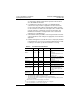
Checking Cable Continuity
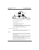
Before checking continuity, disconnect all network cable connectors from
the node devices. Leave the drop cable ground lugs connected to their
site panel grounds. Verify the cable’s end-to-end electrical continuity by
checking the following points, illustrated in Figure 23 on page 33:
• At any node device connector, measure the resistance between pins
2 and 3. This should range between 60 and 80 Ω, including the cable
wire resistance.
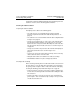
• At each node device connector, check for an open circuit between
pin 2 and pin 1. Then check between pin 3 and pin 1. An open circuit
should exist for both checks.