
Specifications


Bulletin No. VVDED397044US R12/00 Section 1—Installation & Configuration
December 2000 Trunk and Drop Cabling with Taps
© 1998–2000 Schneider Electric All Rights Reserved
31
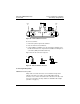
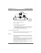
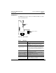
Figure 22: Drop Cable Connections
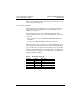
To connect each wire:
1. Remove the plastic cap from the terminal.
2. Place the wire into the terminal slot.
3. Using a Phillips screwdriver, press the cap into the terminal to force
the wire down into the slot. A special tool is available for making these
connections (AMP part number 552714-3).
Figure 21 on page 29 shows the connection sequence.
Connecting the Drop Cable Drain Wire
Install a lug on the drain wire. Tightly crimp or solder the lug to the wire.
Connect the lug to the tap’s screw as shown in Figure 22.
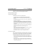
Labeling
After the cable is installed, label the drop cable for easy identification
during future maintenance. Adhesive labels are available commercially
for cable identification.
If a cable layout diagram exists for the installation, label each drop cable
in accordance with the diagram. If a diagram does not exist, prepare one
showing the cable segments and method of identifying them for future
service. Then label the segments accordingly.
Affix the labels to the cables at each network node drop. Place them at a
point that will be visible to maintenance personnel.
GND
WW
O
BLU
Cable Tie
Drop Cable
Drain Wire
Connect drop cable
drain wire at this point.
DO NOT connect drain
wire to ground. Drain is
connected to ground
only at drive controller.