
Specifications


Section 1—Installation & Configuration Bulletin No. VVDED397044US R12/00
Trunk and Drop Cabling with Taps December 2000
30
© 1998–2000 Schneider Electric All Rights Reserved
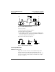
Order a sufficient quantity of drop cables and taps to allow extra ones for
service access and spare parts.
Connecting the Signal Wires
Detailed instructions for stripping the wires and making connections are
enclosed in each tap package. Below is a general description of the
signal wire connections.
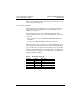
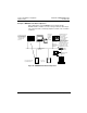
The drop cable contains two sets of twisted-pair signal wires with
separate shield wires. It also has an outer shield drain wire, for a total of
seven wires.
• One set of wires is color-coded WHITE and ORANGE, with a bare
shield wire.
• The other set is WHITE and BLUE, with a bare shield wire.
Before connecting the wires, make sure you have identified the two sets
of twisted-pair wires.
The two white wires are
not interchangeable
. When
you connect the wires, you must connect each wire to its proper terminal.
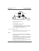
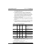
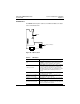
Insert the cable into the tap and secure it with a cable tie. Viewing the tap
as shown in Figure 22 on page 31, connect the wires. The terminals are
marked as illustrated in Table 7.
Table 7: Drop Cable Terminals
Terminal Location Wire Color
O Left ORANGE
W Left Center WHITE
GND Center Shields (both sets of wires)
W Right Center WHITE
BLU Right BLUE