
Specifications


Bulletin No. VVDED397044US R12/00 Section 1—Installation & Configuration
December 2000 Trunk and Drop Cabling with Taps
© 1998–2000 Schneider Electric All Rights Reserved
29
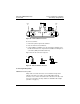
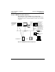
Figure 20: Trunk Cable Connections
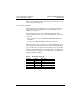
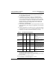
To connect each wire:
1. Remove the plastic cap from the terminal.
2. Place the wire into the terminal slot.
3. Using a Phillips screwdriver, press the cap into the terminal to force
the wire down into the slot. A special tool is available for making these
connections (AMP part number 552714-3).
Figure 21 shows the connection sequence.
Figure 21: Wire Terminal Connection
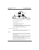
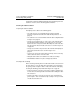
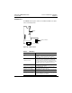
Connecting the Drop Cable
MODBUS PLUS Drop Cable
A drop cable is used at each site to connect between the tap and a
network node device. The cable is preassembled with a 9-pin D
connector on one end for connection to the node device. The other end
is open for connection to the taps. Cables are available in two lengths
(see Table 1 on page 3).
GND
W
BLK
GND
W
BLK
Cable
Tie
Cable
Tie
1
23
Cap
Terminal