
Specifications


Section 1—Installation & Configuration Bulletin No. VVDED397044US R12/00
Trunk and Drop Cabling with Taps December 2000
28
© 1998–2000 Schneider Electric All Rights Reserved
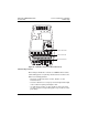
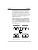
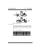
Figure 19: Taps at End Sites
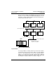
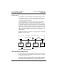
Connecting the Wires
Detailed instructions for stripping the wires and making the connections
are enclosed in each tap package. This section provides a general trunk
cable description of the connections. The trunk cable is connected as
shown in Figure 20 on page 29. The terminals are marked as shown in
Table 6.
Table 6: Trunk Cable Terminals
Terminal Meaning Location Wire Color
GND Network Bus, Ground Top Shield
W Network Bus, White Middle White
BLK Network Bus, Blue or Black Bottom Blue or Black
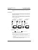
Network
Trunk
Cable
Cable Tie
Jumpers Installed
Network
Trunk
Cable
Jumpers
Installed
Cable
Tie
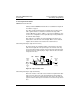
B
W
J1
J2
W
B
J1
J2