
Specifications


Bulletin No. VVDED397044US R12/00 Section 1—Installation & Configuration
December 2000 Trunk and Drop Cabling with Taps
© 1998–2000 Schneider Electric All Rights Reserved
27
Connecting the Trunk Cables
MODBUS PLUS Trunk Cable
Cable specified for MODBUS PLUS trunk use is available from Square D.
See Table 2 on page 3.
The cable should run directly between network device locations. Each
cable segment must be a continuous run between the taps at two
locations. Do not use splices, splitters, or any other configurations such
as star or tree configurations. The only media components permitted are
the network cable and taps.
Plan cable runs according to the horizontal distances between sites.
Trunk cable is ordered in reels of fixed length. Order reels of sufficient
length to allow continuous runs between the network devices.
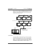
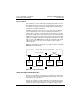
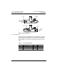
Cable Entry and Jumpers (Taps at In-Line Sites)
At each in-line tap site, install two lengths of trunk cable. Connect the
cable from the right side of the previous tap to the left side of this tap.
Connect the cable from the left side of the next tap to the right side of this
tap. Remove the two internal jumpers. Figure 18 shows the connections
for taps at in-line sites.
Figure 18: Taps at In-Line Sites
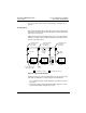
Cable Entry and Jumpers (Taps at End Sites)
At the two end sites on the cable section, install one length of trunk cable
and connect it to either side of the tap. Install the two internal jumpers
between the center posts and the lower two posts at the side of the tap
opposite from the cable. Figure 19 shows the connections for taps at end
sites.
Network
Trunk
Cable
Network
Trunk
Cable
Cable
Tie
Jumpers
Removed
Cable
Tie
To
right side
of
previous
tap
To
left side
of
next tap