
Specifications


Section 1—Installation & Configuration Bulletin No. VVDED397044US R12/00
Trunk and Drop Cabling with Taps December 2000
26
© 1998–2000 Schneider Electric All Rights Reserved
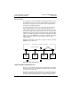
• For each drop cable, provide a service loop to allow the connector to
be connected and disconnected at the network node device without
any strain on the cable. A service loop of 6 in. (152 mm) minimum
radius is adequate for most installations.
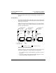
• Install cable ties or clamps on each trunk cable segment as required
for strain relief, to prevent the cable from pulling on the tap.
• Install cable ties or clamps on each drop cable as required for strain
relief, to prevent the cable from pulling on the tap or node device
connector.
• Use additional ties or clamps as required to secure each cable to
prevent flexing or other damage in areas of mechanical motion devices
and traffic.
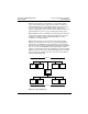
Mounting the Tap
Mount each tap at a location near its node device, preferably outside the
drive controller enclosure. The tap must be near enough to the node
device to allow the drop cable to reach the node device with a service
loop. See Figure 16 for drop cable routing.
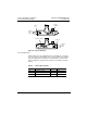
The location must also be accessible for installing the trunk and drop
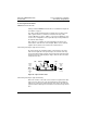
cables and for future maintenance. Figure 17 shows the tap’s outer and
mounting dimensions.
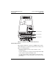
Figure 17: Tap Layout (Cover Open)
4.4 (112)
Hole Diameter
0.2 (5)
3.16 (80.2)
2.2 (56)
Dim: in (mm)
Mounting Centers