
Specifications


Bulletin No. VVDED397044US R12/00 Section 1—Installation & Configuration
December 2000 Trunk and Drop Cabling with Taps
© 1998–2000 Schneider Electric All Rights Reserved
25
sites on the cable section must be removed (open). See Figure 18 on
page 27.
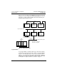
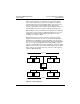
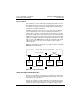
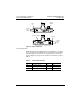
Routing Cables
Figure 16 shows typical cable routing of the network trunk cable between
tap locations. The figure also shows cable drops to several node devices
and service access points.
NOTE: The tap’s internal termination jumpers are connected at the two
end taps of a cable section, and disconnected and removed at each in-
line site on the cable section.
Figure 16: Typical Cable Routing
Referring to Figure 16, route the cable between the site locations of the
node devices. Guidelines for cable routing are described below.
• Use a continuous length of trunk cable between locations. Do not use
any splices.
• At each tap location, allow sufficient trunk cable length for a service
loop to prevent pulling or twisting of the cable.
Node
Device
Node
Device
Service
Access
Point
Node
Device
Termination jumpers
connected in
each end tap
Termination jumpers
connected in
each end tap
End
Location
Drop Cable
Trunk cable
secured in
raceway or
conduit
Strain
Reliefs
Inline
Location
End
Location
Inline
Location
Node device connector
(part of drop cable)
Service
Loop
Termination jumpers
removed from
each inline tap
= Termination Connected
= Termination Disconnected