
Specifications


Section 1—Installation & Configuration Bulletin No. VVDED397044US R12/00
Trunk and Drop Cabling with Taps December 2000
24
© 1998–2000 Schneider Electric All Rights Reserved
Physical Network
The network bus consists of twisted-pair shielded cables that are run in a
direct path between successive nodes. The two data lines in the cable are
not sensitive to polarity; however, this bulletin follows standard wiring
conventions to facilitate maintenance.
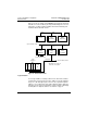
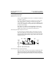
The physical network consists of one or more cable sections, with any
section supporting up to 32 nodes at a maximum cable distance of
1,500 ft (450 m). Sections can be joined by repeater devices to extend
the network’s length and to support up to 64 nodes. The minimum cable
length between any pair of nodes must be at least 10 ft (3 m). Drop cable
length is counted twice towards the 10 ft minimum requirement. The drop
cable is a loop of the MODBUS PLUS cable. The maximum cable length
between two nodes is the same as the maximum section length of
1,500 ft (450 m).
NOTE: The ATV58 drive controller does not support a dual or redundant
MODBUS PLUS cable layout.
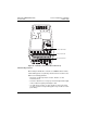
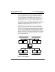
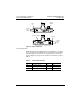
Figure 15: Single Cable Layout
TRUNK AND DROP CABLING WITH TAPS
Nodes are connected to the cable by means of a tap device. This provides
“through” connections for the network trunk cable and “drop” connections
for the cable to the node device.
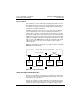
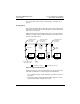
The tap also contains a resistive termination connected by two internal
jumpers. The jumpers of the taps at each end of a cable section must be
connected to prevent signal reflections. The jumpers of taps at in-line
BP85
Bridge
Plus
= Termination Connected
End
Node
Inline
Node
Inline
Node
ATV58
Drive
Controller
= Termination Disconnected
10 ft (3 m) Cable Min.
32 Nodes Max.; 1500 ft (450 m) Cable Max.
CableTaps