
Specifications


Section 1—Installation & Configuration Bulletin No. VVDED397044US R12/00
Network Overview December 2000
22
© 1998–2000 Schneider Electric All Rights Reserved
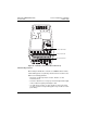
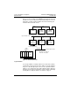
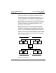
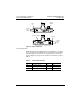
Figure 13 shows an example of two MODBUS PLUS networks. Networks
A and B are host level networks joined by a BP85 Bridge Plus. For more
information, consult the
Modicon Modbus Plus Network Planning and
Installation Guide,
890 USE 100 00
.
Figure 13: Network Overview
Logical Network
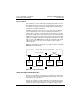
User-assigned addresses identify network nodes. Each node’s address
is independent of its physical site location. Addresses must be within the
range of 1 to 64, although they do not have to be sequential. Duplicate
addresses are not allowed. A device with a duplicate address will not be
allowed to join the network. If it attempts to join the network, it will display
an LED pattern for duplicate address. See Table 9 on page 37.
Up to 64 Nodes Total *
Up to 64 Nodes Total *
Node
10
Node
5
Node
4
Node
23
Node
2
Network B
Network A
Modbus or
Custom Serial Devices
DI/O
Interfaces
PLC
ATV58
Drive
Controller
ATV58
Drive
Controller
RR85
Repeater
BM85
Bridge
Multiplexer
BP85
Bridge
Plus
Local
10
P
L
C
D
I
O
D
I
O
P
S
* Maximum of 32 nodes on
each side of a repeater