
Specifications

Section 1—Installation & Configuration Bulletin No. VVDED397044US R12/00
Hardware Setup December 2000
14
© 1998–2000 Schneider Electric All Rights Reserved
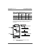
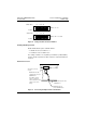
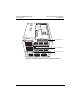
Figure 6: 9-Pin D-Shell Connector, Viewing the End of the Drop
Cable
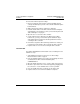
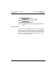
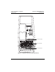
Network Grounding
Connect the shield of the MODBUS PLUS cable to the ground terminal.
Route the cable as shown in Figure 7 on page 15. You must maintain this
connection even if there is no node device connected to the network at
the site (for example, if the drive controller has been temporarily removed
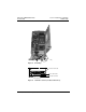
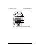
for repair). The ground terminal locations for each ATV58 drive controller
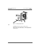
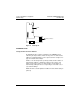
frame size are illustrated in Figures 8–12.
Pin 1 Pin 2 Pin 3
Pin 1: Shielding
Pin 2: Signal
Pin 3: Signal