
Specifications

Bulletin No. VVDED397044US R12/00 Section 1—Installation & Configuration
December 2000 Hardware Setup
© 1998–2000 Schneider Electric All Rights Reserved
13
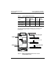
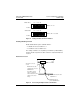
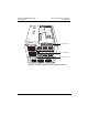
Figure 4: Setting the Drive Controller Address
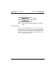
Enabling/Disabling the Card
Enable and disable the option card with switch 7.
• To disable the card, set switch 7 to 1.
• To enable the card, set switch 7 to 0.
The settings of switches 1 to 6 (address) and switch 7 (enable/disable)
become effective only when the drive controller is restarted. Switch 8 is
not used.
Network Connection
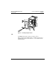
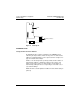
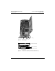
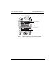
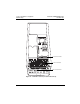
Figure 5: Connecting the Option Card to the Network
1
0
1
0
12345 876
1 2 4 8 16 32
1 2 4 8 16 32
1
0
1
0
12345 876
Position
Address 22 = 1+1+4+16
Switch Value
Position
Switch Value
Address 2 = 1+1
9-pin female connector
on card
MODBUS PLUS cable
equipped with connectors
990NAD219 xx
Note: When using the
network, separate the
network cable from control
cabling, such as motor
wiring.
MODBUS PLUS trunk cable
490NAA271 xx
MODBUS PLUS tap
junction 990NAD230 00