
Specifications

Section 1—Installation & Configuration Bulletin No. VVDED397044US R12/00
Installation December 2000
10
© 1998–2000 Schneider Electric All Rights Reserved
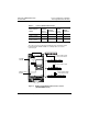
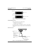
To measure the DC bus capacitor voltage:
1. Disconnect all power from the drive controller including external
control power that may be present on the control board and the option
board terminals.
2. Wait 3 minutes for the DC bus capacitors to discharge.
3. Read the model number of the drive controller from the nameplate
and identify the corresponding (+) and (–) measurement points from
Table 5 and Figure 1 on page 9.
4. Open the door or cover of the drive controller.
5. Set the voltmeter to the 1000 Vdc scale. Measure the voltage
between the (+) and (–) measurement points identified in step 3.
Verify that the DC bus voltage has discharged below 45 V before
servicing the drive controller.
6. If the DC bus capacitors will not discharge below 45 V, contact your
local Square D representative. Do not operate the drive controller.
7. Replace all doors or covers after servicing the drive controller.
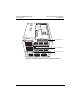
INSTALLATION
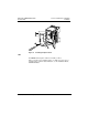
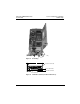
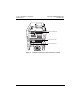
To install the VW3A58302U communication card, consult Figure 2 and
follow these steps:
1. Verify that DC bus voltage is not present. See “Bus Voltage
Measurement Procedure” on page 8.
2. Place the 50/60 Hz switch in the position corresponding to the motor
as indicated in the drive controller installation guide,
VVDED397048US.
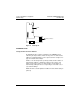
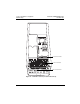
3. Open the flexible protective cover ① over the option card connector.
4. Mount the option card on the control card support by plugging it into
the connector ➁. Secure it with the three screws ➂ provided.
5. Close the flexible protective cover back over the option card.
6. Replace all doors or covers when installation is complete.