
Specifications

Bulletin No. VVDED397044US R12/00 Section 1—Installation & Configuration
December 2000 Bus Voltage Measurement Procedure
© 1998–2000 Schneider Electric All Rights Reserved
9
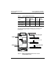
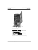
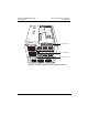
Figure 1: DC Bus Voltage Measurement Point Locations
(ATV58HU09M2 Shown)
Table 5: (+) and (–) Measurement Points
Drive Controller
ATV58•
(+) Measurement Point (–) Measurement Point
Terminal
Block or
Connector
Terminal
Designation
Terminal
Block or
Connector
Terminal
Designation
U09M2• and U18M2• J2 (+) J2 (–)
U29M2• to D12M2•,
U18N4• to D23N4•
J2 PA J18 7
D16M2• to D46M2•,
D28N4• to D79N4•
J2 (+) J2 (–)
+
–
L1 L2 L3 PA PB U V W
L1 L2 + – UVW
L1 L2 L3 PA PB U V W
–
+
+
–
+
–
ATV58•D16M2–D46M2
ATV58•D28N4–D79N4
ATV58•U09M2–U18M2
ATV58•U29M2–D12M2
ATV58•U18N4–D23N4
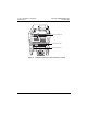
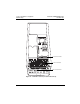
J18-7
J18
Power
Terminal
Block
}
}
}
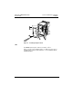
The J18 connector is in the upper left hand corner of the main control
board behind the flexible shield. Use a thin probe to access the
connector pin.
Flexible
Shield
Main Control
Board