Instruction Bulletin VVDED397044US R12/00 December 2000 Raleigh, NC, USA ALTIVAR® 58 Adjustable Speed Drive Controllers MODBUS® PLUS Communication Option VW3A58302U Retain for future use.
DANGER HAZARDOUS VOLTAGE • Read and understand this bulletin in its entirety before installing or operating ALTIVAR 58 drive controllers. Installation, adjustment, repair, and maintenance of the drive controllers must be performed by qualified personnel. • Disconnect all power before servicing the drive controller.
Bulletin No. VVDED397044US R12/00 December 2000 ALTIVAR 58 MODBUS PLUS Communication Option Contents INTRODUCTION . . . . . . . . . . . . . . . . . . . . . . . . . . . . . . . . . . . . . . . . . . . . . . . . . . . . . . . . 3 USING THIS MANUAL . . . . . . . . . . . . . . . . . . . . . . . . . . . . . . . . . . . . . . . . . . . . . . . . . . . . 5 REVISION LEVEL . . . . . . . . . . . . . . . . . . . . . . . . . . . . . . . . . . . . . . . . . . . . . . . . . . . . . . .
ALTIVAR 58 MODBUS PLUS Communication Option Contents Bulletin No. VVDED397044US R12/00 December 2000 Initial Power-Up . . . . . . . . . . . . . . . . . . . . . . . . . . . . . . . . . . . . . . . . . . . . . . . . . . . 33 Configuration . . . . . . . . . . . . . . . . . . . . . . . . . . . . . . . . . . . . . . . . . . . . . . . . . . . . . 33 Example of MODBUS PLUS Network Operation . . . . . . . . . . . . . . . . . . . . . . . . . . . . 34 OPTIMIZING NETWORK PERFORMANCE . . . . . . . . . . . . . . . .
Bulletin No. VVDED397044US R12/00 December 2000 Introduction MODBUS PLUS Communication Option INTRODUCTION The VW3A58302U MODBUS® PLUS Communication Option allows the connection of an ALTIVAR® 58 (ATV58) drive controller to MODBUS PLUS networks. This allows a remote host to control the drive through the network.
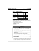
Introduction MODBUS PLUS Communication Option Table 3: Bulletin No. VVDED397044US R12/00 December 2000 Hand/Off/Auto Operators Description Selector switch Collar Contact block Operator Part No. 22 mm 30 mm ZB4BD3 1 — KS42B — 1 ZB4BZ009 1 — ZBE1026P 1 — ZBE1016P 2 — KA32 — 1 KA33 — 1 As a node on a network, the ATV58 drive controller can receive and respond to data messages.
Bulletin No. VVDED397044US R12/00 December 2000 Introduction MODBUS PLUS Communication Option USING THIS MANUAL This manual applies to all ATV58 drive controllers. It has three sections: • Section 1: Installation and Configuration (page 7) • Section 2: MODBUS PLUS Overview (page 39) For register description and address locations refer to the ATV58 Register Access Guide for Communication Networks, VVDED397058US.
Introduction MODBUS PLUS Communication Option 6 Bulletin No.
Bulletin No. VVDED397044US R12/00 December 2000 Section 1—Installation & Configuration Interface Specifications SECTION 1—INSTALLATION & CONFIGURATION RECEIVING, PRELIMINARY INSPECTION, AND STORAGE After receiving the VW3A58302U communication option card: • Ensure that the catalog number printed on the box label is the same as that on the packing slip and corresponding purchase order. Contact your local Square D representative if there are any errors.
Section 1—Installation & Configuration Bus Voltage Measurement Procedure Bulletin No. VVDED397044US R12/00 December 2000 BEFORE INSTALLING THE OPTION CARD WARNING UNINTENDED EQUIPMENT ACTION Read and understand documents VVDED397048US and VVDED397047US before operating the drive controller. Failure to follow this instruction can result in death, serious injury, or equipment damage.
Bulletin No.
Section 1—Installation & Configuration Installation Bulletin No. VVDED397044US R12/00 December 2000 To measure the DC bus capacitor voltage: 1. Disconnect all power from the drive controller including external control power that may be present on the control board and the option board terminals. 2. Wait 3 minutes for the DC bus capacitors to discharge. 3.
Bulletin No. VVDED397044US R12/00 December 2000 Section 1—Installation & Configuration Installation 1 3 2 3 1 0 3 Figure 2: Installing the Option Card LED The MODBUS PLUS option card has one LED (see ② in Figure 3 on page 12). For LED operation, see Table 9 on page 37. For operation of the controller status indicators, see the Installation Guide, VVDED397048US.
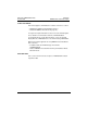
Section 1—Installation & Configuration Hardware Setup Bulletin No. VVDED397044US R12/00 December 2000 2 LED 1 0 1 1 Address Switches 8 Connector Figure 3: Card Layout HARDWARE SETUP Setting the Drive Controller Address An ALTIVAR 58 drive controller is identified on the MODBUS PLUS network by its unique address, which can range from 1 to 64.Select the address by setting DIP switches on the option card. Refer to Figure 4 on page 13 for details and examples.
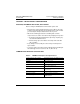
Bulletin No. VVDED397044US R12/00 December 2000 Switch Value Section 1—Installation & Configuration Hardware Setup 1 2 4 8 16 32 1 Position 1 0 Address 2 = 1+1 0 1 2 3 4 5 6 7 8 Switch Value 1 2 4 8 16 32 1 1 0 0 Position Figure 4: Address 22 = 1+1+4+16 1 2 3 4 5 6 7 8 Setting the Drive Controller Address Enabling/Disabling the Card Enable and disable the option card with switch 7. • To disable the card, set switch 7 to 1. • To enable the card, set switch 7 to 0.
Section 1—Installation & Configuration Hardware Setup Pin 1 Bulletin No. VVDED397044US R12/00 December 2000 Pin 2 Pin 3 Pin 1: Shielding Pin 2: Signal Pin 3: Signal Figure 6: 9-Pin D-Shell Connector, Viewing the End of the Drop Cable Network Grounding Connect the shield of the MODBUS PLUS cable to the ground terminal. Route the cable as shown in Figure 7 on page 15.
Bulletin No.
Section 1—Installation & Configuration Hardware Setup Bulletin No.
Bulletin No.
Section 1—Installation & Configuration Hardware Setup Bulletin No.
Bulletin No. VVDED397044US R12/00 December 2000 Section 1—Installation & Configuration Hardware Setup Control Terminals Power Terminals Ground Terminal Figure 12: Terminal Locations (Product Frame Size 7) Cable Routing Practices When wiring the ATV58 drive controllers to a MODBUS PLUS network, follow all wiring practices required by national and local electrical codes. Observe the following guidelines: • Avoid areas of high temperature, moisture, vibration, or other mechanical stress.
Section 1—Installation & Configuration Hardware Setup Bulletin No. VVDED397044US R12/00 December 2000 • Avoid sources of electrical interference that can induce noise into the cable. Use the maximum practicable separation from such sources. When planning cable routing within a building, follow these guidelines: • Maintain a minimum separation of 3.
Bulletin No. VVDED397044US R12/00 December 2000 Section 1—Installation & Configuration Network Overview NETWORK OVERVIEW MODBUS PLUS is a Local Area Network system designed for industrial control applications. Up to 32 node devices can connect directly to the network bus cable over a length of up to 1,500 ft (450 m) including drop lengths. Repeater devices are used to extend the cable distance to its maximum of 6,000 ft (1,800 m) and the node count to a maximum of 64.
Section 1—Installation & Configuration Network Overview Bulletin No. VVDED397044US R12/00 December 2000 Figure 13 shows an example of two MODBUS PLUS networks. Networks A and B are host level networks joined by a BP85 Bridge Plus. For more information, consult the Modicon Modbus Plus Network Planning and Installation Guide, 890 USE 100 00.
Bulletin No. VVDED397044US R12/00 December 2000 Section 1—Installation & Configuration Network Overview Network nodes function as peer members of a logical ring, gaining access to the network upon receipt of a token frame. The token is a grouping of bits that is passed in rotating address sequence from one node to another. Each network maintains its own token rotation sequence, independent of other networks. Where multiple networks are joined by bridges, the token is not passed through the bridge device.
Section 1—Installation & Configuration Trunk and Drop Cabling with Taps Bulletin No. VVDED397044US R12/00 December 2000 Physical Network The network bus consists of twisted-pair shielded cables that are run in a direct path between successive nodes. The two data lines in the cable are not sensitive to polarity; however, this bulletin follows standard wiring conventions to facilitate maintenance.
Bulletin No. VVDED397044US R12/00 December 2000 Section 1—Installation & Configuration Trunk and Drop Cabling with Taps sites on the cable section must be removed (open). See Figure 18 on page 27. Routing Cables Figure 16 shows typical cable routing of the network trunk cable between tap locations. The figure also shows cable drops to several node devices and service access points.
Section 1—Installation & Configuration Trunk and Drop Cabling with Taps Bulletin No. VVDED397044US R12/00 December 2000 • For each drop cable, provide a service loop to allow the connector to be connected and disconnected at the network node device without any strain on the cable. A service loop of 6 in. (152 mm) minimum radius is adequate for most installations. • Install cable ties or clamps on each trunk cable segment as required for strain relief, to prevent the cable from pulling on the tap.
Bulletin No. VVDED397044US R12/00 December 2000 Section 1—Installation & Configuration Trunk and Drop Cabling with Taps Connecting the Trunk Cables MODBUS PLUS Trunk Cable Cable specified for MODBUS PLUS trunk use is available from Square D. See Table 2 on page 3. The cable should run directly between network device locations. Each cable segment must be a continuous run between the taps at two locations. Do not use splices, splitters, or any other configurations such as star or tree configurations.
Section 1—Installation & Configuration Trunk and Drop Cabling with Taps Bulletin No. VVDED397044US R12/00 December 2000 Jumpers Installed Cable Tie Network Trunk Cable J2 J1 B W Jumpers Installed J2 J1 Cable Tie Network Trunk Cable B W Figure 19: Taps at End Sites Connecting the Wires Detailed instructions for stripping the wires and making the connections are enclosed in each tap package. This section provides a general trunk cable description of the connections.
Bulletin No. VVDED397044US R12/00 December 2000 Section 1—Installation & Configuration Trunk and Drop Cabling with Taps Cable Tie Cable Tie BLK BLK W W GND GND Figure 20: Trunk Cable Connections To connect each wire: 1. Remove the plastic cap from the terminal. 2. Place the wire into the terminal slot. 3. Using a Phillips screwdriver, press the cap into the terminal to force the wire down into the slot. A special tool is available for making these connections (AMP part number 552714-3).
Section 1—Installation & Configuration Trunk and Drop Cabling with Taps Bulletin No. VVDED397044US R12/00 December 2000 Order a sufficient quantity of drop cables and taps to allow extra ones for service access and spare parts. Connecting the Signal Wires Detailed instructions for stripping the wires and making connections are enclosed in each tap package. Below is a general description of the signal wire connections.
Bulletin No. VVDED397044US R12/00 December 2000 Section 1—Installation & Configuration Trunk and Drop Cabling with Taps Drop Cable Drain Wire Cable Tie BLU O W GND W Connect drop cable drain wire at this point. DO NOT connect drain wire to ground. Drain is connected to ground only at drive controller. Figure 22: Drop Cable Connections To connect each wire: 1. Remove the plastic cap from the terminal. 2. Place the wire into the terminal slot. 3.
Section 1—Installation & Configuration Trunk and Drop Cabling with Taps Bulletin No. VVDED397044US R12/00 December 2000 Complete the network installation labeling by properly labeling each site’s cabinet or enclosure, device mounting panel, and device. Checking the Cable Installation Inspecting the Cable Installation Visually inspect the cable for the following points: • The cable runs are consistent with the physical and electrical protection requirement described in “Cable Routing Practices” on page 19.
Bulletin No. VVDED397044US R12/00 December 2000 Section 1—Installation & Configuration Parameter Setup • At each connector, check the continuity between pin 1 and the MODBUS PLUS cable shield ground point on the heat sink. Direct continuity should not be present. • Check for proper termination and insulation of individual drop twisted pair shields. If any check point fails, inspect the cable and all connections for damage or miswiring, and correct the condition.
Section 1—Installation & Configuration Parameter Setup Bulletin No. VVDED397044US R12/00 December 2000 Example of MODBUS PLUS Network Operation Figure 24 illustrates a typical MODBUS PLUS network with two ALTIVAR 58 drive controllers as nodes. The figure illustrates that a single node controls the drive controller by implicit reservation of the command semaphore. Specific transfer with peer cop enabled in the ALTIVAR 58 drive controller creates a command node (Node 1).
Bulletin No. VVDED397044US R12/00 December 2000 Section 1—Installation & Configuration Optimizing Network Performance Command message to drive controller 1 (Node 4) is refused since Modicon node 2 has PLC Node 3 reserved the command semaphore of drive controller 1. HMI sends MB Plus commands to reserve the command semaphore in drive controller 1.
Section 1—Installation & Configuration Optimizing Network Performance Bulletin No. VVDED397044US R12/00 December 2000 use this function during normal network operation. This function is also called NTO, No Time-Out. 4. Use distributed control where possible. The ALTIVAR 58 drive controller has a large number of application functions that can be used in conjunction with network communications.
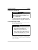
Bulletin No. VVDED397044US R12/00 December 2000 Section 1—Installation & Configuration Diagnostics DIAGNOSTICS The MODBUS PLUS option card has one LED that indicates the status of the communication link. 2 LED 1 0 1 1 Address Switches 8 Connector Figure 26: LED Location Table 9: LED States State of LED Meaning Off Card Disabled: Switch 7 is in ON state ILF Fault: A communication problem exitst between the communication option card and the drive controller.
Section 1—Installation & Configuration Diagnostics Bulletin No.
Bulletin No. VVDED397044US R12/00 December 2000 Section 2—Modbus Plus Overview ALTIVAR® 58 Registers and Data Exchange SECTION 2—MODBUS PLUS OVERVIEW INTRODUCTION The MODBUS PLUS option card allows an ALTIVAR 58 (ATV58) drive controller to function as a node on a MODBUS PLUS network. This section explains how information is exchanged between the drive controller registers and other nodes on the network.
Section 2—Modbus Plus Overview MSTR Block Bulletin No. VVDED397044US R12/00 December 2000 As a node on a MODBUS PLUS network, the ATV58 drive controller cannot initiate messages, but all of its command (read and write), adjustment (read and write), and display (read only) registers can be read by other networked devices through messaging at any time, even when the drive controller is running.
Bulletin No. VVDED397044US R12/00 December 2000 Section 2—Modbus Plus Overview MSTR Block MSTR Block Structure Inputs MSTR has two control points (see Figure 27 on page 41): • Top node input — enables the instruction when top node input is ON. • Middle node input — terminates the active operation when middle node input is ON. Outputs MSTR can produce three possible outputs (see Figure 27): • Top node output — echoes the state of the top node input (goes ON while the instruction is active).
Section 2—Modbus Plus Overview MSTR Block Bulletin No. VVDED397044US R12/00 December 2000 Top Node Content The 4x register entered in the top node is the first of nine contiguous holding registers that comprise the control block (see Table 11).
Bulletin No. VVDED397044US R12/00 December 2000 Section 2—Modbus Plus Overview Peer Cop Read and Write MSTR Operations An MSTR write operation transfers data from a controlling device to the drive controller. An MSTR read operation transfers data from the drive controller to a controlling device on the network. Control Block Table 12 shows the information contained in the top node of the MSTR control block in a read or write operation.
Section 2—Modbus Plus Overview Peer Cop Bulletin No. VVDED397044US R12/00 December 2000 1. Select Peer Cop and press ENT. The peer cop status appears. Select YES using the ▲▼ keys and press ENT. 2. Select Control Node and press ENT. Using the ▲▼ keys, enter the number of the node from which the peer cop data is to be received. 3. Select Number Registers and press ENT. Using the ▲▼ keys, enter the number of variables to be received.
Bulletin No. VVDED397044US R12/00 December 2000 Section 2—Modbus Plus Overview Peer Cop Table 13 lists the control and adjustment variables mapped through peer cop transfers.
Section 2—Modbus Plus Overview Global Data Transmission Bulletin No. VVDED397044US R12/00 December 2000 GLOBAL DATA TRANSMISSION When a networked node holds the token, it may communicate with other nodes on the link and gather network statistics. When a node releases the token, it appends up to 32 sixteen-bit words of global data to the token frame. All nodes present on the network detect this data packet, and any appropriately programmed node can extract the data and record it in its global database.
Bulletin No. VVDED397044US R12/00 December 2000 Table 14: Section 2—Modbus Plus Overview Global Data Transmission Display Register Mapping w/ Global Data (Continued) Address of Global Data Drive Order Controller Number Variable Designation Description 11 483 DF1 Register of active faults No. 1 12 484 DF2 Register of active faults No. 2 13 462 DP1 Number of past fault No. 1 14 463 EP1 Status of past fault No. 1 15 464 DP2 Number of past fault No.
Section 2—Modbus Plus Overview Global Data Transmission Bulletin No. VVDED397044US R12/00 December 2000 3. Power up the drive controller. 4. Adjust the five MODBUS PLUS parameters using the operator keypad or the PC software (part number VW3A8104). — TLP: Peer cop time-out. Factory setting 1 s. Change the setting if necessary. Disconnecting the PLC or the drive controller for this duration will stop the motor and the drive controller will switch to CNF fault mode. — CDN: Control node.
Bulletin No. VVDED397044US R12/00 December 2000 Section 2—Modbus Plus Overview Command Semaphore — Change TLP using the operator keypad or the PC software. — Perform steps 6 and 7 to set the motor to RUN FORWARD. 12. The other nodes on the network can read all of the drive controller registers via message handling. They cannot write to the registers used in peer cop (in this example, they are the five registers CMD, LFR, CMI, HSP, LSP). However, they can write to other adjustment registers (ACC, DEC, etc.
Section 2—Modbus Plus Overview Command Semaphore Bulletin No. VVDED397044US R12/00 December 2000 of the drive controller to the MODBUS port device by setting bits 8 and 15 of control word CMD to 1. Among MODBUS PLUS devices, only one device can write to the drive controller’s control words. If peer cop data is enabled within the drive controller, it receives its peer cop data from a designated control device.
Bulletin No. VVDED397044US R12/00 December 2000 Section 2—Modbus Plus Overview Hand/Off/Auto (HOA) • through a PLC or other controller connected to the fast serial link via a communication card NOTE: The operator keypad takes priority over the terminals. When the communication network has control of the drive, the setpoints and commands are controlled via the network and cannot be modified by the terminals, the keypad, or any device connected to the RS-485 MODBUS serial port.
Section 2—Modbus Plus Overview Hand/Off/Auto (HOA) Bulletin No. VVDED397044US R12/00 December 2000 before the MODBUS PLUS communication board has initialized and assumed control. This can result in unintended equipment operation. When the control switch is in the hand or off position, the drive controller must be placed into the forced local mode .
Bulletin No. VVDED397044US R12/00 December 2000 Section 2—Modbus Plus Overview Local and Remote Local and Remote The ATV58 drive controller can be commanded in local and remote control modes.
Section 2—Modbus Plus Overview Forced Local Bulletin No. VVDED397044US R12/00 December 2000 WARNING UNINTENDED EQUIPMENT ACTION When in forced local mode, all commands from the communication ports are ignored. Failure to consider the implications of unanticipated operation can result in death, serious injury, or equipment damage. When the logic input is not active (low), all control of the drive is transferred to the network if wired as shown in Figures 28 or 29.
Bulletin No. VVDED397044US R12/00 December 2000 Section 2—Modbus Plus Overview Control Registers Protection of Adjustment and Configuration Access A configuration semaphore has not been provided in order to ensure read-only access to the configuration and adjustment parameters. Any processing unit can access the configuration and adjustment parameters. Access Protection by Forced Local Writing of Command registers is blocked during forced local.
Section 2—Modbus Plus Overview Control Registers Bulletin No.
Bulletin No. VVDED397044US R12/00 December 2000 Index Numerics F N 50/60 Hz switch 10 fast serial link 49, 51 NTO 36 forced local 52 A address drive controller 12 P G parameter communication 33 global database duplicate 22 max. number of words 46 peer cop setup 47–49 attenuating filters 20 mapping words 44 max.
91598103011102 W915981030111A02 ALTIVAR® 58 Adjustable Speed Drive Controllers MODBUS® PLUS Communication Option VW3A58302U Square D Company 8001 Highway 64 East Knightdale, NC 27545 1-888-SquareD (1-888-778-2733) www.SquareD.com Bulletin No. VVDED397044US R12/00 February 2001 Replaces VVDED397044US dated 9/98.