
Installation guide


72 Estimating Network Performance
890 USE 100 00
3.7 A Sample MSTR Communication
Every Modbus Plus device has a peer processor that controls network
communication. Collectively the peer processors in all of the networked
devices establish and maintain the token rotation, the transmission
and receipt of messages, and acknowledgements. In a programmable
controller, the peer processor transfers message data to and from the
MSTR functions in your ladder logic.
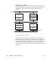
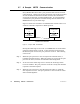
Figure 31 shows two controllers on a Modbus Plus network. Here is an
estimate of the time required for a Read operation.
CONTROLLER
A
PEER
PROCESSOR
CONTROLLER
B
PEER
PROCESSOR
MODBUS PLUS NETWORK
REQUEST >
< RESPONSE
Figure 31 Sample READ Communication
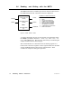
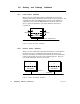
During the ladder logic scan in unit A, an MSTR block is executed that
specifies a Read request to unit B. At the end of the block execution,
the Read request is sent to the peer processor in unit A. The following
events occur:
Step 1 When the peer processor in unit A acquires the network token, it
transmits the Read request. When the request is received by the peer
processor in unit B, it sends an immediate acknowledgement.
Step 2 At the end of the ladder logic scan in unit B, the incoming transac-
tions are handled. The peer processor in unit B is ready with the data
response to the Read request.
Step 3 When the peer processor in unit B acquires the token, it sends the
data response to unit A. The peer processor in unit A sends an imme-
diate acknowledgement.