
Installation guide


Estimating Network Performance
890 USE 100 00
71
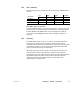
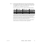
For example, in a data Read or Write operation, the Control Block
layout is as follows:
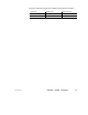
Register Content
4x Operation Type 1 = Write
2 = Read
4x + 1 Storage for Returned Error Status Code (if an error occurs)
x + 2 Data Block Length 4
4x + 3 Start of the Data Area in the Destination Device
4x + 4 Modbus Plus Routing Path 1
4x + 5 Modbus Plus Routing Path 2
4x + 6 Modbus Plus Routing Path 3
4x + 7 Modbus Plus Routing Path 4
4x + 8 Modbus Plus Routing Path 5
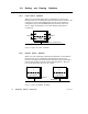
The Control Block register at 4x + 2 specifies the length of the data
area for the read or write operation. For example, if this register
contains a value of 32 decimal, that many registers of data will be
transferred in the operation.
The Control Block register at 4x + 3 defines the starting location of the
data buffer in the destination device. Its contents are an offset value
(not an absolute address). For example, a value of 1 specifies reference
40001 in a programmable controller. The offset can be incremented in
successive MSTR operations to move large areas of data.
Data Area Start is a 4x reference that is the starting register in a block
of upto100 consecutive registers that will be used as the local data
buffer in the Read or Write. If the operation is a Read, the incoming
data from the destination device will be stored into this buffer. For a
Write, the buffer contents will be sent to the destination device.
Data Area Size is an absolute value in the range 1 ... 100 decimal. It
specifies the maximum quantity of registers to be allocated for the
MSTR function’s data area.