
Installation guide


54 Elements of Network Planning
890 USE 100 00
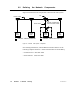
V Between nodes 2 ... 4, the difference between cables A and B is also
600 ft (180 m). This exceeds the maximum allowable difference of
500 ft (150 m).
NODE NODE NODE
1 2 4
CABLE A
CABLE B
300 ft
(90 M)
900 ft
(270 M)
NODE
3
450 ft
(135 M)
150 ft
(45 M)
450 ft
(135 M)
150 ft
(45 M)
NOT
TO
SCALE
Figure 26 Dual-Cable Layout: Illegal Lengths
Note that the cable A-to-B difference only applies to node connections
on the same cable section. If node 4 were a Repeater or Bridge Plus, for
example, the cables on the other side of that node would be totally
independent of the cables in Figure 26, for measurement purposes.
2.3.5 Estimating Cable Run Distances
Your cable layout planning should provide information to the installers
that will show the cut length of each segment in the cable run. Before
the cable is cut at each drop location, the following factors should be
considered:
V The cable routing must provide for installation of strain reliefs to
prevent the cable’s weight from pulling on its connector at the node
device. The cable should be routed adjacent to a frame, panel, or
other stable structure to properly secure strain reliefs against its
weight. Allow sufficient cable length for this routing.
V You must provide a service loop at each node device to allow future
servicing of the device without placing stress on the cable or
connector. A service loop of 6 in (15 cm) minimum radius is
adequate for most panel mounting layouts.