
Installation guide


Introducing the Modbus Plus Network
890 USE 100 00
41
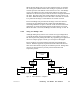
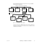
Figure 24 summarizes the layout of port devices in a typical BM85
user-programmed application.
MODBUS PLUS NETWORK (UP TO 64 NODES)
BM85
BRIDGE
MULTIPLEXER
CPU
BARCODE
= MODBUS PORT
READER
1 2 3 4
DISPLAY
MODBUS
DEVICE
SCALE
CPUCPU
Figure 24 Userprogrammed BM85 Application
As shown in the figure, a Modbus master or slave device could also be
attached at a serial port if the user-defined code in the BM85 included
a Modbus protocol handler.