
Installation guide


Introducing the Modbus Plus Network
890 USE 100 00
35
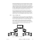
When the first Bridge (22) receives the original message, it examines
the routing field and determines that routing is required to its other
network port (the next address in the field is not a zero). The Bridge
removes its address from the routing field, shifting the remaining
addresses in the field one place to the left and zerofilling the field from
the right. This places the next routing address (20) into position 1 of
the field. When the Bridge receives the token to transmit on network
B, it passes the message to node address (20) on that network.
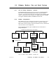
The second Bridge (20) processes the message in the same manner,
removing its own address from the routing field and shifting the
remaining addresses one place to the left. Node 12 becomes the final
destination, as all the remaining contents of the field are now zeros.
When the token is received, the Bridge sends the message to node 12.
1.12.2 Using the Bridge Plus
Although adding many nodes to one network is a legal configuration,
you might find that message throughput is unacceptably slow due to
the time required for passing the token. By organizing your application
into more compact groups of nodes, you can improve throughput.
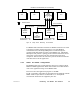
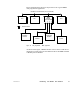
Figure 21 shows a basic hierarchical approach using Bridge Plus
devices. With this approach, separate networks contain the devices
that must communicate rapidly in an industrial process. Bridge Plus
devices join the networks to provide process information and
supervisory control.
NODE
BP85
BRIDGE
PLUS
BP85
BRIDGE
PLUS
HOST AND
SUPERVISORY
NODE NODE NODE
TIMECRITICAL
PROCESS CONTROL
TIMECRITICAL
PROCESS CONTROL
NODE
Figure 21 Basic Hierarchical Configuration