
Installation guide

34 Introducing the Modbus Plus Network
890 USE 100 00
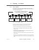
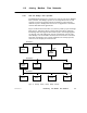
If a data message intended for a remote node is received at one of the
Bridge’s ports, the Bridge stores the message, and then forwards it to a
node address on the next network as soon as it has received the token
to transmit on that network.
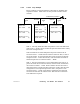
Each message frame contains routing information that allows it to be
passed through successive Bridges to a final destination node on a
remote network. The routing path is specified when the message is
created by the user’s application program. Messages can be routed to a
final destination up to four networks away from the originating node.
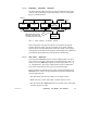
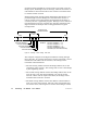
Figure 20 shows an example of the routing path field in a typical
message frame.
MESSAGE FRAME
ROUTING
PATH
ROUTING ADDRESS 1
ROUTING ADDRESS 2
ROUTING ADDRESS 3
ROUTING ADDRESS 4
ROUTING ADDRESS 5
MODBUS PLUS
EXAMPLE: ROUTING ADDRESS 1 = 22
ROUTING ADDRESS 2 = 20
ROUTING ADDRESS 3 = 12
ROUTING ADDRESSES 4 AND 5
ARE ZERO (NO FURTHER ROUTING)
START
END
Figure 20 Message Frame Routing Path Field
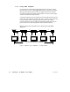
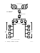
The examples in Figure 19 and Figure 20 illustrate routing through
three networks. If a message originates at node 5 on network A, and is
intended for node address 12 on network C, the message will be
forwarded as described below.
V The first routing address contains the Bridge address (22) on the
originating node’s network. The message will be sent to this Bridge
by the originating station.
V The second routing address contains the Bridge address (20) on the
next network. Note that the first Bridge is at node 25 on this
network. When node 25 acquires the token, the message will be
forwarded from node 25 to node 20.
V The third routing address contains the address of the destination
node (12) on the final network. The rest of the routing path field
will contain zeros, indicating that no further forwarding is needed.