
Installation guide


Introducing the Modbus Plus Network
890 USE 100 00
33
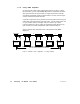
1.12 Joining Modbus Plus Networks
1.12.1 How the Bridge Plus Operates
The BP85 Bridge Plus device connects as a node on each of two Modbus
Plus networks. The Bridge operates as an independent node on each
network, receiving and passing tokens according to each network’s
address sequence. Bridge Plus devices are not applicable to networks
used for Distributed I/O applications.
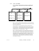
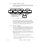
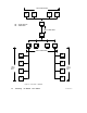
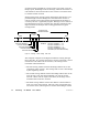
Figure 19 shows three networks (A, B, and C) joined by a pair of Bridge
Plus devices. The figure shows a single-cable network for simplicity.
The Bridge Plus also supports dual-cable layouts. One Bridge appears
on network A at node address 22, and on network B at node 25. The
other Bridge is on network B at node 20, and on network C at node 20.
Note that each Bridge’s two network addresses are entirely separate,
and can be set uniquely for each network.
NETWORK A
NETWORK B
NODE
20
NODE
22
NODE
25
BP85
BRIDGE
PLUS
NODE NODE
NODE
NODE
NODE
NETWORK C
NODE
20
NODE NODE NODENODE
NODE
BP85
BRIDGE
PLUS
Figure 19 Message Routing Through Multiple Networks