
Installation guide


Introducing the Modbus Plus Network
890 USE 100 00
31
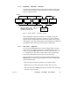
1.1 1.3 Expanding Dual-cable Networks
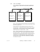
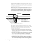
On dual-cable networks, repeaters must be placed between the same
node devices, maintaining a logical symmetry to the two cable paths.
Figure 17 illustrates this.
NODE
5
NODE
4
NODE
6
RR85
REPEATER
NODE
NODE
3
RR85
REPEATER
CABLE A
CABLE B
REPEATERS ARE PLACED
BETWEEN THE SAME PAIR
OF NODES ON EACH CABLE
NODENODENODE
Figure 17 Placing Repeaters on Dual-cable Networks
This configuration is proper because the two repeaters are placed
between the same nodes. Placing a repeater on one path, without a
repeater at the corresponding point on the other path, is not a proper
configuration. Note that the two physical cable lengths can be different,
provided the logical symmetry of the network is maintained.
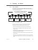
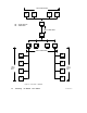
1.1 1.4 NonLinear Expansion
You can connect RR85 Repeaters to create multiple paths, so long as
each section is run along a linear path (no branches to the cable). In
effect, you can use RR85 Repeaters to create the equivalent of star or
tree configurations. This can be useful where a linear configuration
may not be practical due to the layout of your plant facility.
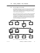
Figure 18 shows an example of nonlinear network expansion using
RR85 Repeaters. This is a legal configuration because it satisfies the
network requirements:
V Not more than 32 nodes are present on any single section
V Each section is a linear cable path of 1500 ft (450 m) or less
V Not more than three RR85 Repeaters are present in the cable path
between any pair of nodes.