
Installation guide


Introducing the Modbus Plus Network
890 USE 100 00
29
1.1 1 Expanding the Network
1.1 1.1 Linear Expansion
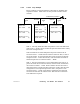
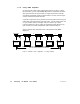
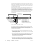
The simplest network configuration consists of two or more nodes
connected to a single section. Figure 15 shows four nodes connected in
a basic dual-cable configuration.
PROGRAMMABLE
CONTROLLER
PROGRAMMABLE
CONTROLLER
PROGRAMMABLE
CONTROLLER
NODE
5
NODE
64
NODE
10
NETWORK
ADAPTER
NODE
2
UP TO 32 NODES MAX., 1500 ft (450 M) CABLE MAX.
10 ft (3 M) CABLE MIN.
500 ft (150 M) CABLE MAX. DIFFERENCE, CABLE A TO B
MEASURED BETWEEN ANY PAIR OF NODES
CABLE A
CABLE B
Figure 15 Basic Configuration Example
The basic configuration in Figure 15 will satisfy the network
requirements if all of the following specifications are met:
V Not more than 32 nodes are connected to the network cable
V The total endtoend length of each network cable is 1500 ft
(450 m) or less
V The difference in length between cables A and B is 500 ft (150 m)
or less, between any pair of nodes
V The length of each cable segment (between a pair of nodes) is 10 ft
(3 m) or more
V The proper type of impedance termination is used at each node site
(tap’s internal jumpers removed at inline sites, and installed at end
sites).