
Installation guide


24 Introducing the Modbus Plus Network
890 USE 100 00
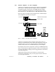
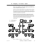
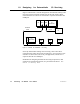
1.9 Designing for Deterministic I/O Servicing
Figure 13 illustrates a network designed for deterministic timing of I/O
processes. The I/O network consists only of the CPU and I/O drops.
A User Interface (UI) device is connected to a separate network at the
NOM port.
CPU NOMPS
I/O
MODULES
D
I
O
TIO TIO
UI
MODBUS
PLUS
2
3 4 5
TIO
6
MODBUS
PLUS
2
3
I/O
MODULES
Figure 13 Network for Deterministic I/O T iming
For truly deterministic timing of I/O servicing, reserve the CPU’s
network for the nodes used in I/O servicing only. If you require a User
Interface or other non-I/O device in your application, connect it to a
separate network at a NOM port.
Guidelines for designing networks for servicing I/O processes, with
estimates of network performance, are provided in the Modbus Plus
Network I/O Servicing Guide.