
Installation guide

Introducing the Modbus Plus Network
890 USE 100 00
9
1.4 Overview of the Physical Network
The network bus consists of twisted-pair shielded cable that is run in a
direct path between successive nodes. The two data lines in the cable
are not sensitive to polarity, however a standard wiring convention is
followed in this guide to facilitate maintenance.
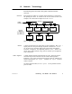
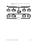
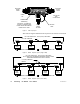
The network consists of one or more cable sections, with any section
supporting up to 32 nodes at a maximum cable distance of 1500 ft
(450 m). Sections can be joined by Repeaters to extend the network
length and to support up to 64 nodes.
The minimum cable length between any pair of nodes must be at least
10 ft (3 m). The maximum cable length between two nodes is the same
as the maximum section length of 1500 ft (450 m).
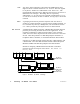
On dual-cable networks, the cables are known as cable A and cable B.
Each cable can be up to 1500 ft (450 m) long, measured between the
two extreme end devices on a cable section. The difference in length
between cables A and B must not exceed 500 ft (150 m), measured
between any pair of nodes on the cable section.
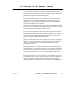
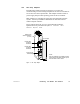
Nodes are connected to the cable by means of a tap device, supplied by
Modicon. This provides ‘through’ connections for the network trunk
cable, ‘drop’ connections for the cable to the node device, and a
grounding terminal.
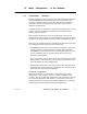
The tap also contains a resistive termination that is connected by two
internal jumpers. The tap at each end of a cable section requires both
of its jumpers to be connected to prevent signal reflections. All of the
taps that are inline on the cable section require their jumpers to be
removed (open).
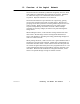
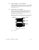
Figure 5 illustrates a tap at an inline site. Two lengths of trunk cable
are installed. When a tap is installed at the end site of a cable section,
only one length of trunk cable is routed to the tap. It can enter at
either side of the tap. The jumpers are connected to the signal pins at
the opposite side of the tap to provide the network termination.